Soil moisture sensor with long battery life

a technology of soil moisture sensor and battery life, applied in the field of agricultural technology, can solve the problems of unsatisfactory short battery life and continuous consumption of power by measurement circuitry, and achieve the effect of avoiding electrolysis and corrosion

Inactive Publication Date: 2010-02-04
CAMENZIND HANS
View PDF5 Cites 5 Cited by
  • Summary
  • Abstract
  • Description
  • Claims
  • Application Information

AI Technical Summary

Benefits of technology

[0011]In a more specific embodiment, the moisture sensing element is of resistive type in that its resistance is a function of its moisture content. The sensor circuitry, while being powered by a DC voltage, drives the moisture sensing element with voltages of alternating polarity to measure the soil moisture while avoiding electrolysis and corrosion at the moisture sensing element.

Problems solved by technology

All of these inventions tend to use complex circuitry and high frequencies which result in, when they are battery powered, an undesirable short battery life.
As all of these inventions of capacitive or resistive measurement continuously measure the soil moisture content, their measurement circuitry continuously consumes a corresponding amount of power that tends to drain the battery.

Method used


Image

  • Soil moisture sensor with long battery life
  • Soil moisture sensor with long battery life
  • Soil moisture sensor with long battery life

Examples


Embodiment Construction

[0023]The description above and below plus the drawings contained herein merely focus on one or more currently preferred embodiments of the present invention and also describe some exemplary optional features and / or alternative embodiments. The description and drawings are presented for the purpose of illustration and, as such, are not limitations of the present invention. Thus, those of ordinary skill in the art would readily recognize variations, modifications, and alternatives. Such variations, modifications and alternatives should be understood to be also within the scope of the present invention.

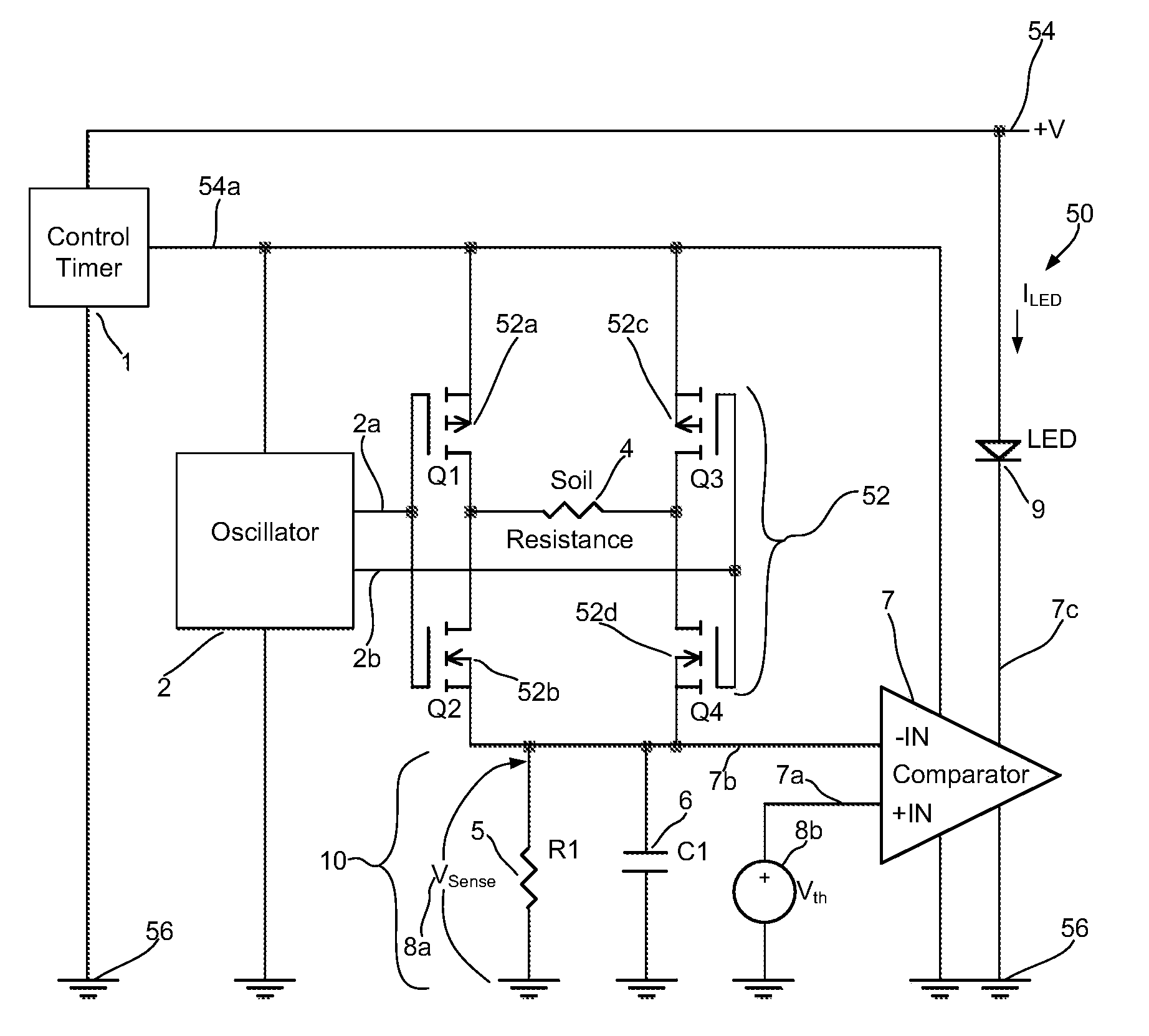
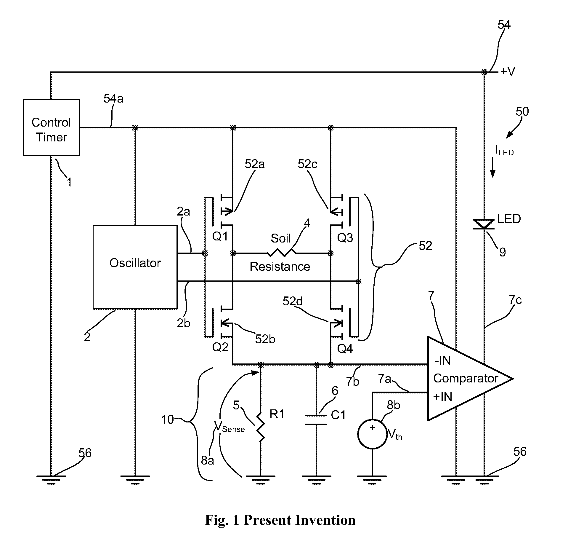
[0024]FIG. 1 is a functional block diagram illustrating the power-efficient electronic soil moisture sensor 50 of the present invention. In this embodiment, the power-efficient electronic soil moisture sensor 50 uses a resistive moisture sensing element 4 with its resistance being a function of its moisture content. In a typical application, the resistive moisture sensing element 4 is e...


PUM

PropertyMeasurementUnit
frequencyaaaaaaaaaa
poweraaaaaaaaaa
soil moistureaaaaaaaaaa

Abstract

A power-efficient soil moisture sensor includes:
  • A moisture sensing element.
  • An alarm device.
  • Sensor circuitry for measuring soil moisture and activating the alarm device when soil moisture reaches a threshold.
  • A powered control timer. The control timer powers the sensor circuitry with a low duty cycle, defined as TON/TOFF with TON/TOFF<<1, hence saving an average consumed power.
  • The alarm device can be an LED and the moisture sensing element is of resistive type. The sensor circuitry drives the moisture sensing element with AC voltages to measure soil moisture while avoiding electrolysis and corrosion at the moisture sensing element. As the measured soil moisture approaches a threshold the sensor circuitry flashes the LED with a gradually increasing intensity. The alarm device can also be an audible speaker (SPK). As the measured soil moisture approaches a threshold, the sensor circuitry pulses the SPK with a gradually increasing volume.

Description

CROSS REFERENCE TO RELATED APPLICATIONSFIELD OF INVENTION[0001]This invention relates generally to the field of agricultural technology. More specifically, the present invention is directed to the electronic measurement of soil moisture content.BACKGROUND OF THE INVENTION[0002]Generally two methods have been used to measure the soil moisture content: capacitive and resistive. Examples of the capacitive method are described in U.S. Pat. No. 3,771,548 to Rauchwerger, U.S. Pat. No. 4,657,039 to Bireley et al, U.S. Pat. No. 4,683,904 to Iltis, U.S. Pat. No. 4,850,386 to Bireley, U.S. Pat. No. 5,424,649 to Gluck at al, U.S. Pat. No. 5,445,178 to Feuer, and U.S. Pat. No. 7,170,302 to Lee. All of these inventions tend to use complex circuitry and high frequencies which result in, when they are battery powered, an undesirable short battery life.[0003]The resistive sensing method is less complex. Examples are U.S. Pat. No. 2,437,134 to Smith, U.S. Pat. No. 3,979,667 to Cornes, and U.S. Pat. ...

Claims


Application Information

Patent Timeline
Patent Type & Authority Applications(United States)
IPC IPC(8): G01N27/04
CPCG01N33/246
Inventor CAMENZIND, HANS
Owner CAMENZIND HANS
Why Eureka
Try Eureka