
Monitor video accumulation system

Active Publication Date: 2010-02-04
RAKUTEN GRP INC
View PDF6 Cites 10 Cited by
  • Summary
  • Abstract
  • Description
  • Claims
  • Application Information

AI Technical Summary

Benefits of technology

[0031]In the surveillance video accumulation system having the stated structure, the surveillance camera unit that has a shooting zone that the subject is expected to enter next starts the encoding that uses only the intra frame prediction. Accordingly, even if the accumulation of the video data is started immediately after the surveillance camera unit is selected, it is possible to accumulate the data encoded by the intra frame prediction.
[0032]Therefore, all the accumulated video data can be played back as long as the predicted surveillance camera unit has been selected.
[0033]The selector of the video accumulation unit may further transmit, to the one of the surveillance camera units, selection information showing that the one of the surveillance camera units has been selected by the selector, and on receipt of the selection information, the encoder of the one of the surveillance camera units may start encoding the video data of the subject of shooting, according to a prediction encoding method that selectively uses either intra frame prediction or inter frame prediction.
[0034]With the stated structure, the normal prediction encoding method is set again when the accumulation of the video data is started according to the selection of the surveillance camera unit that has a shooting zone that the subject is expected to enter next. As a result, it is possible to reduce the total amount of the data to be accumulated.
[0035]This is because the data mount in the case of the encoding with use of only the intra frame prediction is much greater than the data amount in the case of the encoding with use of the inter frame prediction in addition.
[0036]The structure also reduces the bandwidth usage required for the data transmission.

Problems solved by technology

However, even if the transmission of the pictures, beginning with the picture encoded with use of the intra frame prediction, is started immediately after the detection of the designation of (i.e. the switching to) one of the surveillance cameras, it is impossible to completely avoid the decoding failure of some of the pictures of the video data that is being recorded.
This drawing shows that a decoding failure is caused even though the camera unit has immediately generated an I picture after the switching.

Method used


Image

  • Monitor video accumulation system
  • Monitor video accumulation system
  • Monitor video accumulation system

Examples


embodiment

Outline

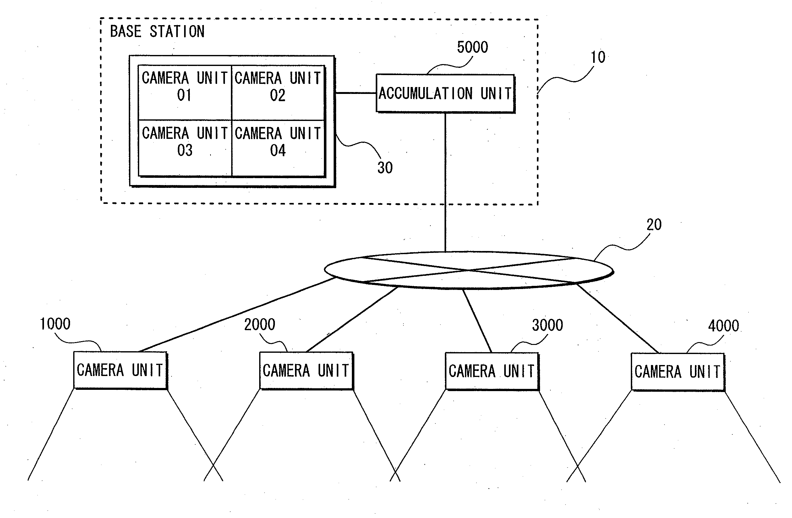
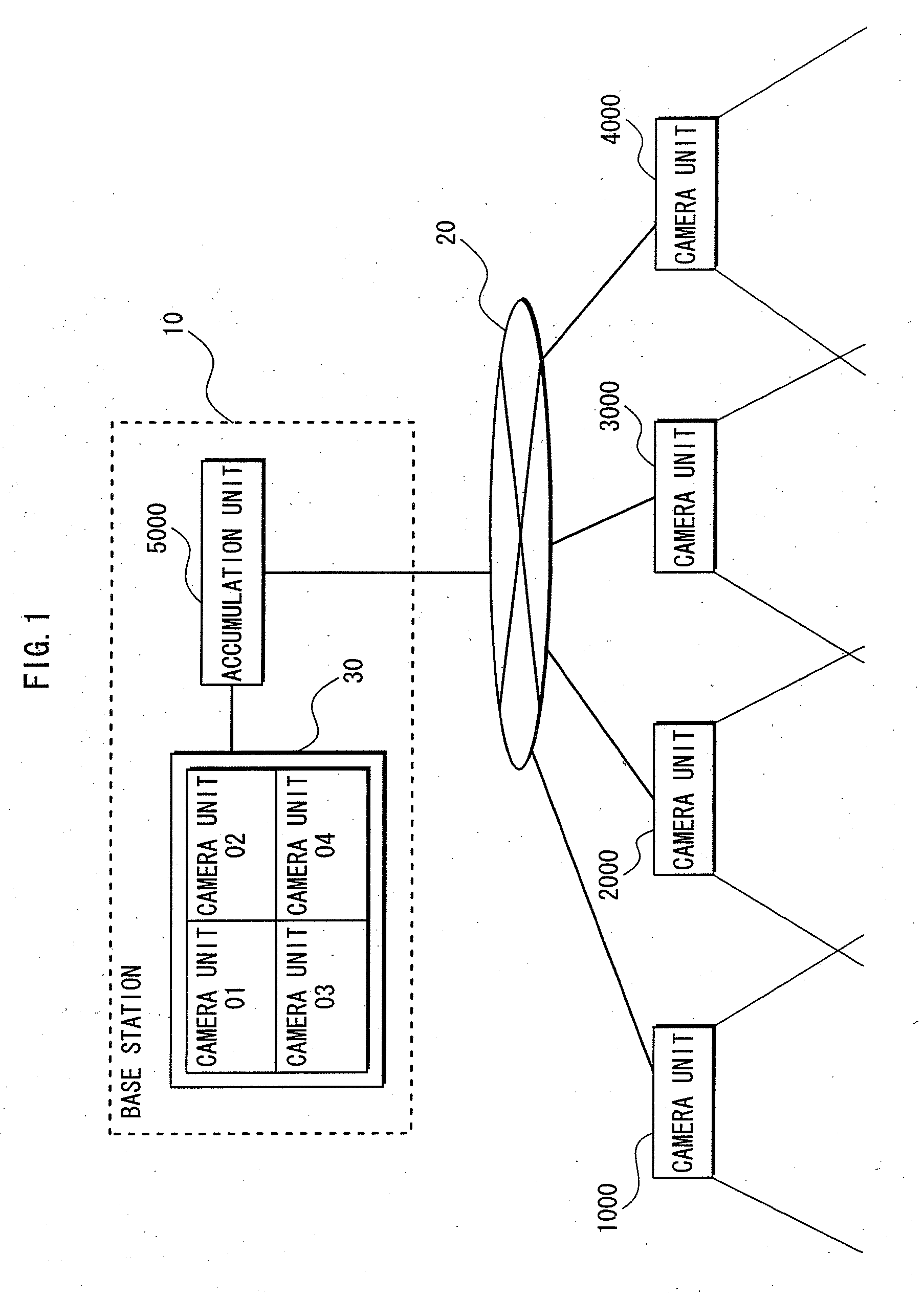
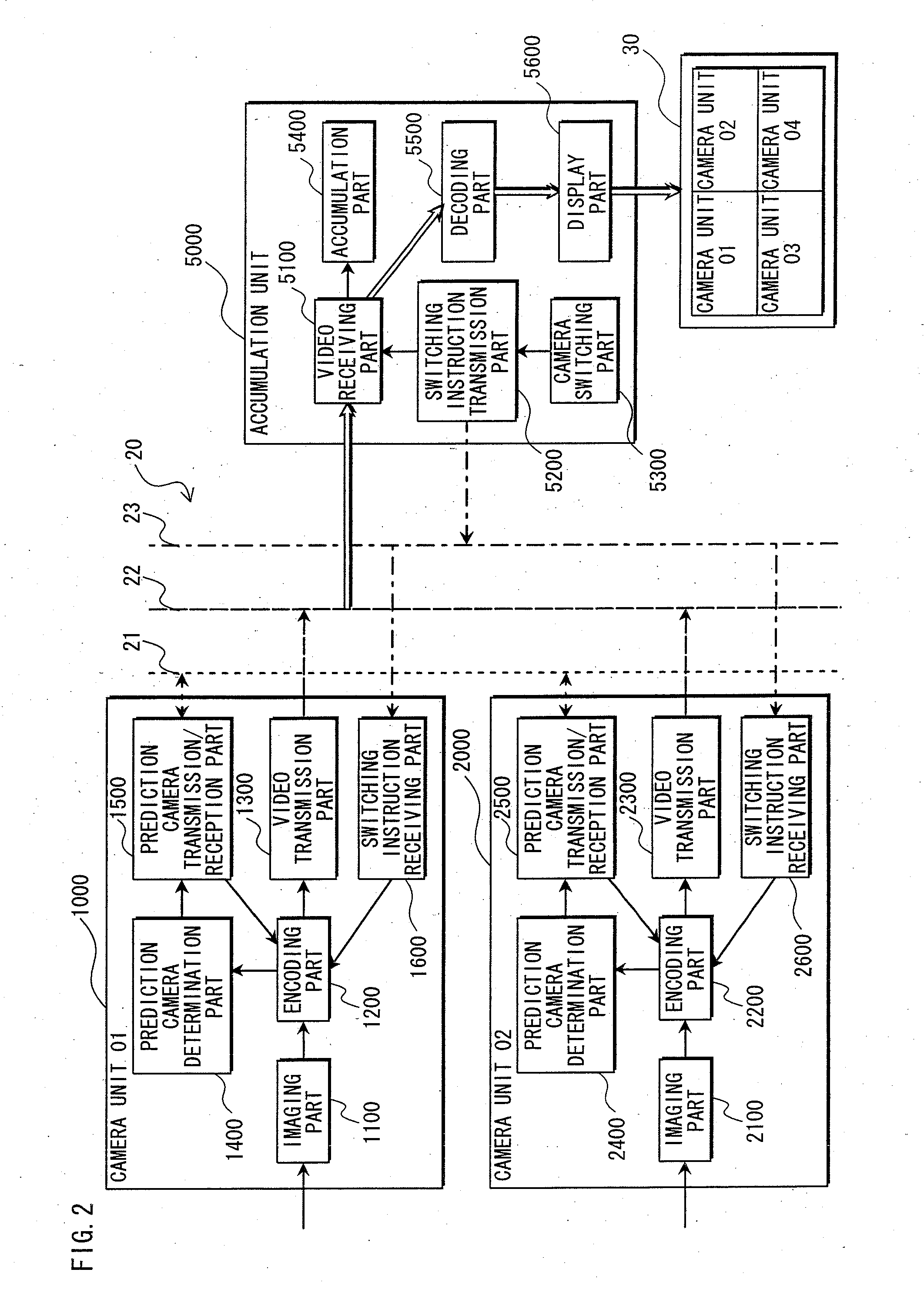
[0066]A surveillance video accumulation system pertaining to the present invention predicts the direction in which the subject moves, and instructs a surveillance camera that is shooting toward the direction (hereinafter called the “prediction camera”) to start encoding with use of only the intra frame prediction before the beginning of the accumulation of video data from the prediction camera.

[0067]The monitor screen that the warden is watching is displaying the videos from the camera units with a little delay. Therefore, the prediction camera prepares an encoded video by using only the intra frame prediction, in order to make up the gap caused by the delay, so that the accumulation can be started at any time.

[0068]Accordingly, if the video from the prediction camera is designated on the monitor, only pictures that have been encoded by the intra frame prediction will be recorded, and pictures that can not be decoded will not be recorded. This means that the playback of the r...


PUM


Abstract

A surveillance video accumulation system pertaining to the present invention includes a plurality of surveillance camera units and a video accumulation unit that are connected with each other via a network. Among pieces of video data that have been encoded according to a prediction encoding method and transmitted from all the surveillance camera units, the video accumulation unit accumulates video data transmitted from a selected one of the surveillance camera units. Before the selection, if specified as a surveillance camera unit that is expected to shoot a subject, each of the surveillance camera units encodes video data of the subject based only on intra frame prediction and transmits the encoded video data to the accumulation unit.

Description

TECHNICAL FIELD[0001]The present invention relates to a surveillance video accumulation system that accumulates surveillance videos, which are pieces of encoded moving picture data. In particular, the present invention relates to a video accumulation technique for recording video data of a moving subject while switching among a plurality of camera units.BACKGROUND ART[0002]Conventionally, surveillance has been conducted with use of surveillance cameras installed in buildings. For example, a warden monitors monitor windows which display videos sent from the surveillance cameras, and records video images of a suspicious individual or the like, if any.[0003]In such surveillance, when the suspicious individual goes out of a monitor window, i.e. goes out of a shooting zone of a single surveillance camera, the warden manually designates the monitor windows one by one to record the video images of the suspicious individual. With such operations, only video images displayed in the designate...

Claims


Application Information

Patent Timeline
IPC IPC(8): H04N7/18
CPCG08B13/19676H04N5/268H04N7/0122H04N7/181H04N19/577H04N19/61H04N19/107H04N19/162H04N19/172
Inventor KAJITA, SATOSHIFUCHIGAMI, IKUO
Owner RAKUTEN GRP INC
Features
  • Generate Ideas
  • Intellectual Property
  • Life Sciences
  • Materials
  • Tech Scout
  • Unparalleled Data Quality
  • Higher Quality Content
  • 60% Fewer Hallucinations
Learn More