
Method and Apparatus for Relocating a Header Compression Context in a Wireless Communication System

a wireless communication system and header compression technology, applied in the field of wireless communication system methods and apparatus, can solve the problems of inefficient link usage, meant to update the context, and become a challenging task

Active Publication Date: 2010-02-04
TELEFON AB LM ERICSSON (PUBL)
View PDF6 Cites 38 Cited by
  • Summary
  • Abstract
  • Description
  • Claims
  • Application Information

AI Technical Summary

Benefits of technology

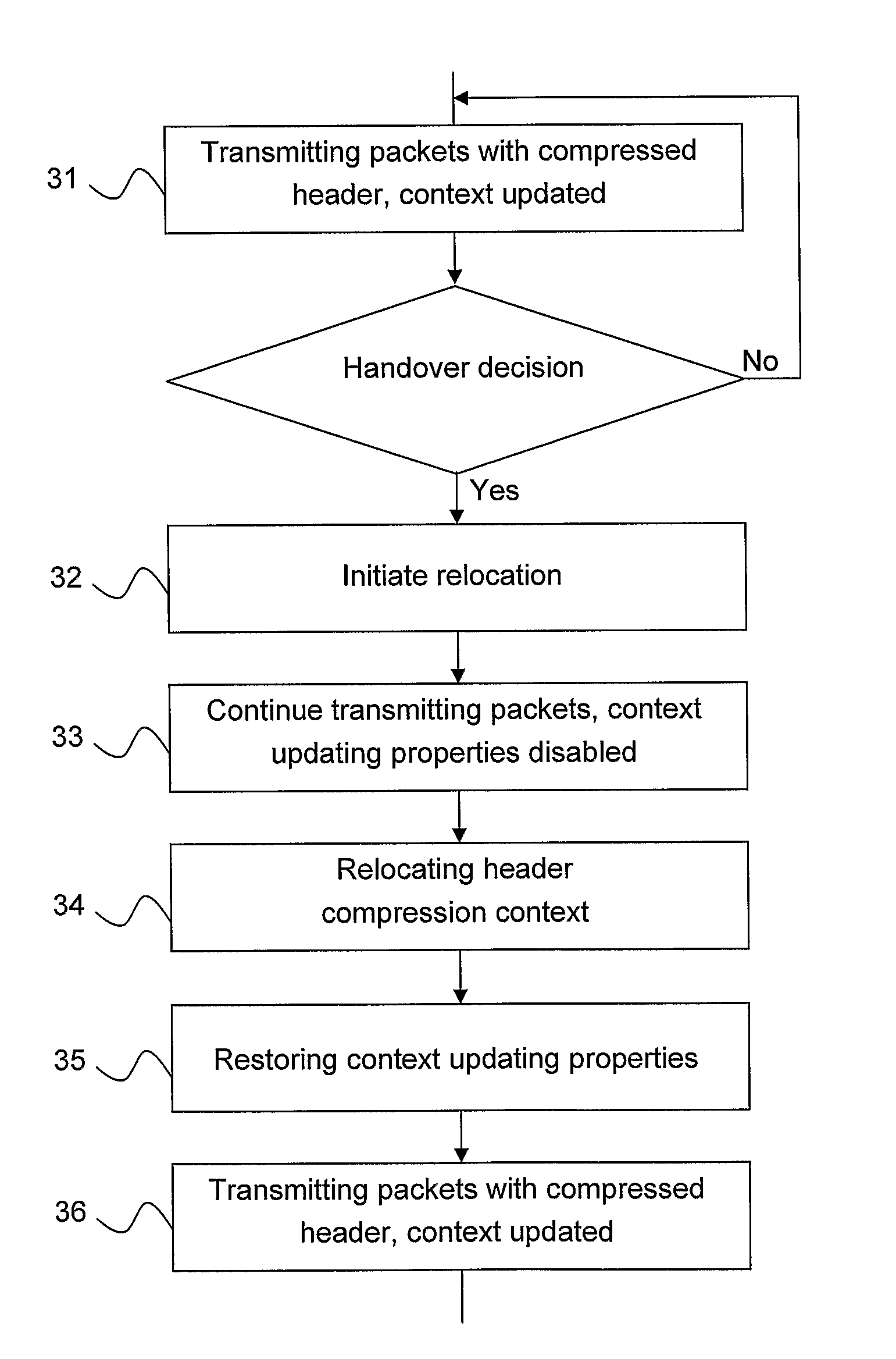
[0056]Accordingly, one objective with the present invention is to provide an improved method of relocating a header compression context of data packets from a source communication network node to a target communication network node during a mobility event in a communication network system, in which said data packets comprising said compressed headers are transmitted initially between a compression endpoint in said user equipment and a compression endpoint in said source communication network node and after said mobility event between a compression endpoint in said user equipment and a compression endpoint in said target communication network node over a radio interface.
[0060]A further objective with the present invention is to provide an improved method in a user equipment of relocating a header compression context of data packets from a source communication network node to a target communication network node during a mobility event in a communication network system, in which said data packets comprising said compressed headers are transmitted initially between a compression endpoint in said user equipment and a compression endpoint in said source communication network node and after said mobility event between a compression endpoint in said user equipment and a compression endpoint in said target communication network node over a radio interface.
[0062]A yet further objective with the present invention is to provide an improved user equipment for relocating a header compression context of data packets from a source communication network node to a target communication network node during a mobility event in a communication network system, in which said data packets comprising said compressed headers are transmitted initially between a compression endpoint in said user equipment and a compression endpoint in said source communication network node and after said mobility event between a compression endpoint in said user equipment and a compression endpoint in said target communication network node over a radio interface.
[0067]to synchronize the context relocation based on compression endpoints, not based on relocation endpoints as in prior art; this enables relocation process of a context that is not based on acknowledgement between compression endpoints. It also allows compression in the source to continue even under the relocation process.

Problems solved by technology

Due to the tremendous success of the Internet, it has become a challenging task to make use of the Internet Protocol (IP) over all kinds of links.
However, because of the fact that the headers of the IP protocols are rather large, it is not always a simple task to make this come true for narrow band links, for example wireless cellular links.
As an example, consider ordinary speech data transported by the protocols (IP, UDP, RTP) used for Voice-over-IP (VoIP), where the header may represent about 70% of the packet -resulting in a very inefficient usage of the link.
One can usually realize a header compression scheme (such as a ROHC Profile) as a state machine and the challenging task is to keep the compressor and decompressor states, called contexts, consistent with each other, while keeping the header overhead as low as possible.
However, most packet types used with the secure reference principle are self-contained and thus not meant to update the context.
Restarting compression requires that a number of uncompressed headers are sent; this may not be sufficiently efficient.
What type of data, under what format and how to have the relocation process interact with the header compression algorithm is a very complex issue, one that a close analysis of prior art reveals has not been properly addressed.
The impact of the above characteristics of the state-of-the-art solution(s) is that the interruption time during a mobility event cannot be minimized, and as a consequence of stopping compression is that no packets can be transmitted from the source node.
Relocation may not be possible either without some additional delay for preparing the context, and waiting for acknowledgement from the decompressor.

Method used


Image

  • Method and Apparatus for Relocating a Header Compression Context in a Wireless Communication System
  • Method and Apparatus for Relocating a Header Compression Context in a Wireless Communication System
  • Method and Apparatus for Relocating a Header Compression Context in a Wireless Communication System

Examples


Embodiment Construction

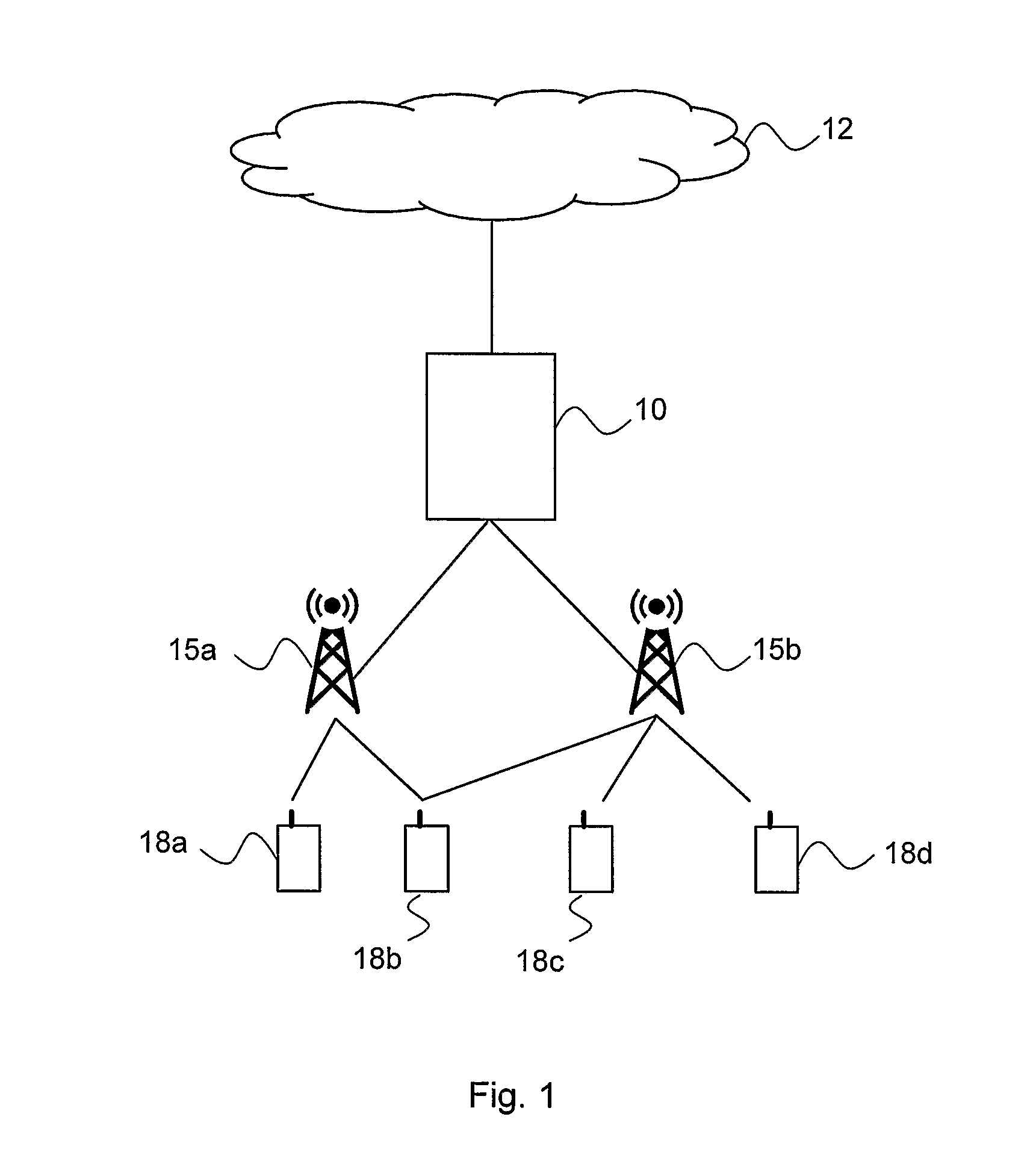
[0094]FIG. 1 depicts a communication system, such as a Wideband Code Division Multiple Access (WCDMA) system, including a Radio Access Network (RAN), such as the UMTS Terrestrial Radio Access Network (UTRAN) architecture, comprising at least one Radio Base Station (RBS) (or Node B) 11a-b, connected to one or more Radio Network Controllers (RNCs) 10 (only one shown in FIG. 1). The RAN is connected over an interface to a Core network (CN) 12, which may be a connection-oriented external CN such as the Public Switched Telephone Network (PSTN) or the Integrated Services Digital Network (ISDN), and / or a connectionless external CN as the Internet.

[0095]The RAN and the CN 12 provide communication and control for a plurality of user equipments (UE) 18a-d. The UEs 18 each uses downlink (DL) channels and uplink (UL) channels to communicate with at least one RBS 15 over a radio or air interface.

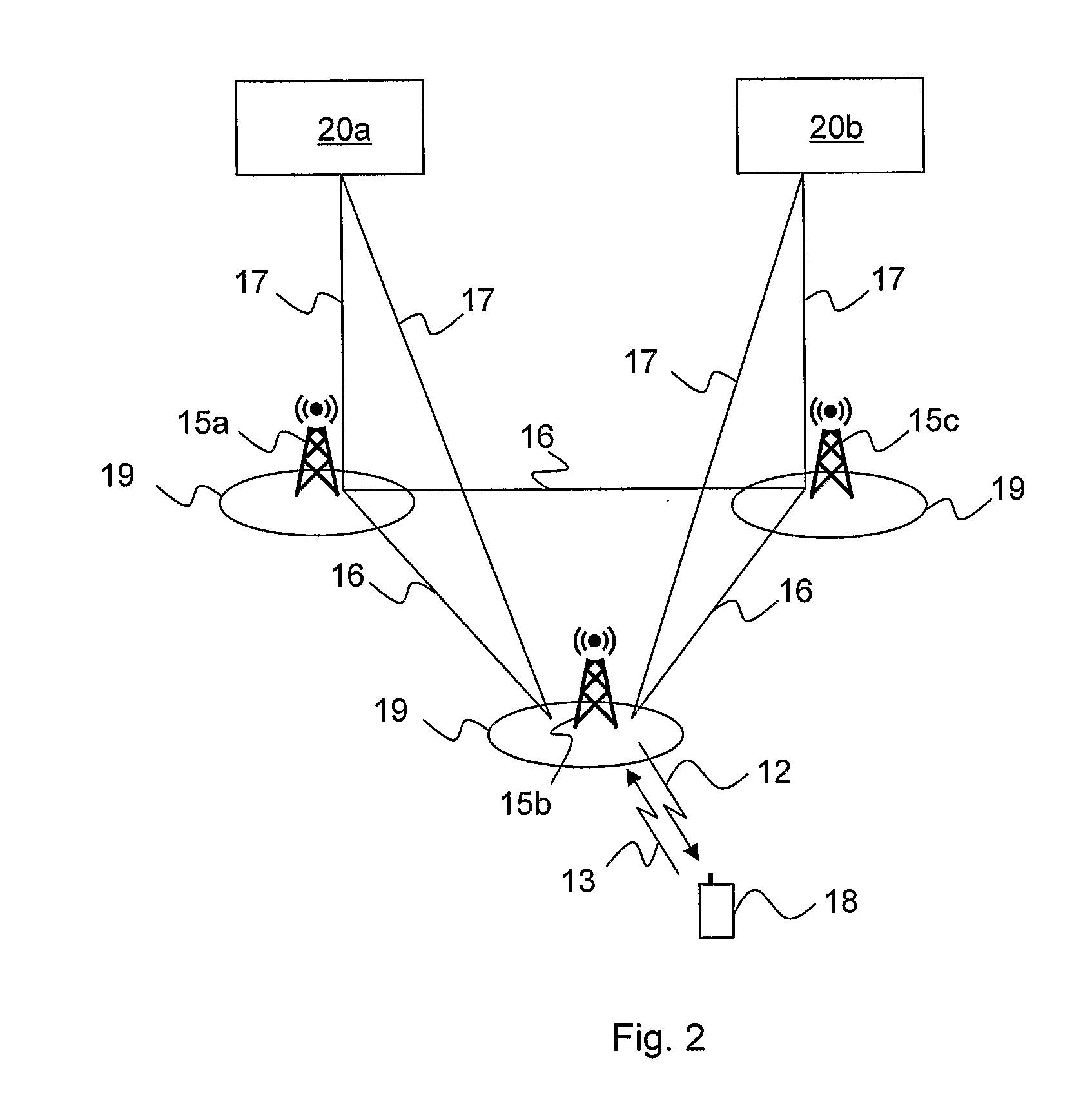
[0096]Another communication system, such as a Long Term Evolution (LTE) system is shown in FIG. 2, in...


PUM


Abstract

The present invention relates to a method and an apparatus for relocating a header compression text, wherein the context updating properties of each individual header during the relocation process is disabled.

Description

TECHNICAL FIELD[0001]The present invention relates to a method and an apparatus in a wireless communication system and, particularly to an apparatus allowing for relocating a header compression text as well as a method for such relocation.BACKGROUND[0002]Due to the tremendous success of the Internet, it has become a challenging task to make use of the Internet Protocol (IP) over all kinds of links. However, because of the fact that the headers of the IP protocols are rather large, it is not always a simple task to make this come true for narrow band links, for example wireless cellular links. As an example, consider ordinary speech data transported by the protocols (IP, UDP, RTP) used for Voice-over-IP (VoIP), where the header may represent about 70% of the packet -resulting in a very inefficient usage of the link.[0003]The term header compression (HC) (defined further below) comprises the art of minimizing the necessary bandwidth for information carried in headers on a per-hop basi...

Claims


Application Information

Patent Timeline
Patent Type & Authority Applications(United States)
IPC IPC(8): H04L12/28H04W72/00H04J3/24H04L69/04H04L69/22H04W28/06H04W36/00
CPCH04W28/06H04L69/22H04L69/04H04W36/0033
Inventor PELLETIER, GHYSLAIN
Owner TELEFON AB LM ERICSSON (PUBL)
Learn More