Radio receiving apparatus and radio receiving method

a technology of receiving apparatus and receiving method, which is applied in the direction of electrical equipment, radio transmission, transmission, etc., can solve the problems of affecting the local directivity, the inability to recover from the state of local directivity adjustment, and the inability to actively receive interfering signals, so as to avoid the deterioration of the reception sensitivity of the desired signal and suppress the im interference

Inactive Publication Date: 2010-02-04
RENESAS ELECTRONICS CORP +1
View PDF19 Cites 17 Cited by
  • Summary
  • Abstract
  • Description
  • Claims
  • Application Information

AI Technical Summary

Benefits of technology

[0020]As described above, the radio receiving apparatus according to the second exemplary aspect of the present invention is capable of updating processing for the tap coefficients based on the adaptive algorithm and performing exceptional updating of at least one of the tap coefficients in accordance with the detection of the occurrence of the IM interference. Thus, when the IM interference occurs, the tap coefficients can be forcibly updated so that the null direction of the

Problems solved by technology

Accordingly, it is difficult for the radio receiving apparatus disclosed in JP 5-327571 A to avoid the deterioration of the reception sensitivity of the desired signal under the reception conditions in which the IM interference is occurring.
However, even when the reception directivity is adjusted in accordance with a known adaptive algorithm, the reception level of the desired signal may be attenuated, which may lead to an inappropriate operation of actively receiving interfering signals.
This is because, in the case of adjusting the reception directivity using a known adaptive algorithm, when the signal intensity of each of two interferin

Method used


Image

  • Radio receiving apparatus and radio receiving method
  • Radio receiving apparatus and radio receiving method
  • Radio receiving apparatus and radio receiving method

Examples


first exemplary embodiment

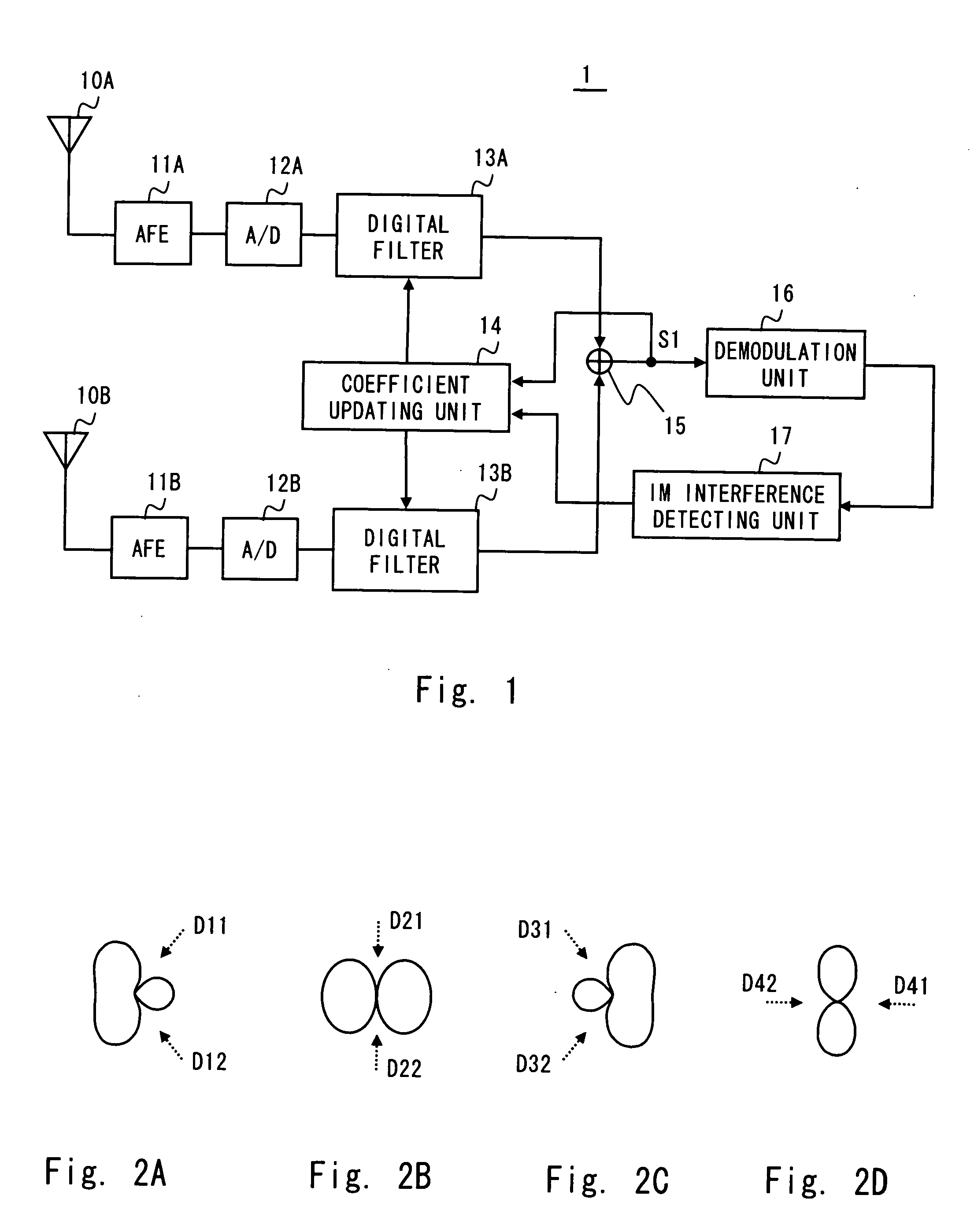
[0035]A radio receiving apparatus 1 according to a first exemplary embodiment of the present invention adjusts amplitudes and phases of received signals received by a plurality of antenna elements, and then combines the received signals. The radio receiving apparatus 1 changes the adjustment amount of the amplitudes and phases of the received signals, to thereby make it possible to change the reception directivity of the plurality of antenna elements.

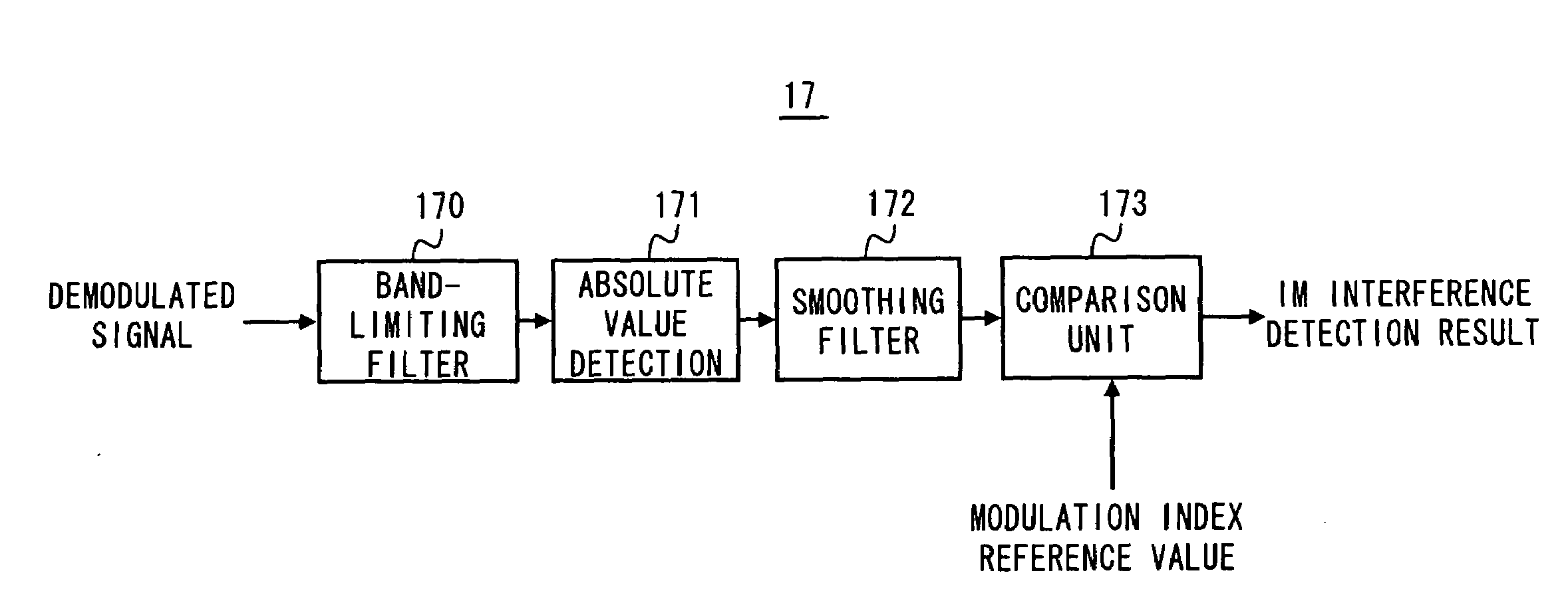
[0036]FIG. 1 is a block diagram showing a configuration example of the radio receiving apparatus 1. Components of the radio receiving apparatus 1 shown in FIG. 1 are described below. Antenna elements 10A and 10B each receive a radio signal. An analog front-end (AFE) 11A performs analog signal processing including band limitation of the radio signal received by the antenna element 10A, conversion of the radio signal into an intermediate frequency signal (IF signal), and amplification of the IF signal. An AFE 11B performs analog signal pr...

second exemplary embodiment

[0059]A radio receiving apparatus 2 according to a second exemplary embodiment of the present invention changes the reception directivity pattern of the antenna elements 10A and 10B so that the null direction is changed according to a detection of the occurrence of the IM interference as well as a judgment result of the quality of the demodulated signal.

[0060]FIG. 5 is a block diagram showing the radio receiving apparatus 2. A quality determining unit 28 shown in FIG. 5 determines how many components, which cause the reception quality to be lowered, are contained in the demodulated signal. Upon detection of the degradation of the reception quality such as the degradation of an S / N ratio, the quality determining unit 28 outputs a control signal to the coefficient updating unit 14 in a similar manner as the IM interference detecting unit 17.

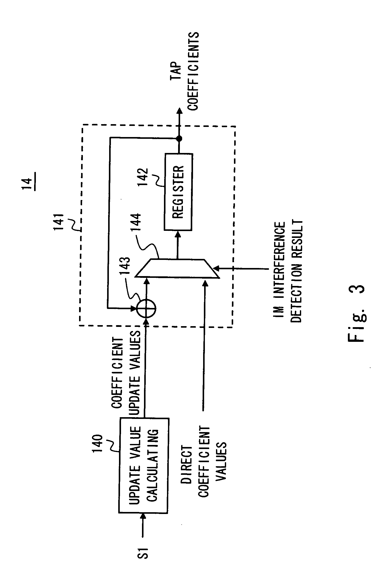
[0061]The control signal output from the IM interference detecting unit 17 or the quality determining unit 28 is fed to the coefficient updating u...

third exemplary embodiment

[0064]A radio receiving apparatus 3 according to a third exemplary embodiment of the present invention is a modified example of the radio receiving apparatus 2. The radio receiving apparatus 3 differs from the radio receiving apparatus 2 in the mechanism for changing the directivity pattern of the antenna elements 10A and 10B.

[0065]FIG. 7 is a block diagram showing a configuration example of the radio receiving apparatus 3. The radio receiving apparatus 3 shown in FIG. 7 differs from the radio receiving apparatus 2 shown in FIG. 5 in the following points. That is, the digital filter 13B is omitted in the radio receiving apparatus 3 shown in FIG. 7. Meanwhile, in the radio receiving apparatus 3 shown in FIG. 7, an adder 31, a subtractor 32, and a switch 33 are disposed at the previous stage of the digital filter 13A. A coefficient updating unit 34 adaptively updates the tap coefficients by using an output signal S2 of the digital filter 13A.

[0066]The adder 31 adds digital IF signals ...


PUM


Abstract

A radio receiving apparatus includes a detection unit and a directivity changing unit. The detection unit detects an occurrence of intermodulation interference to a desired signal demodulated based on received signals received by a plurality of antenna elements. The directivity changing unit changes a reception directivity pattern of the plurality of antenna elements to another pattern having a null direction different from a null direction obtained before the directivity pattern is changed, in accordance with detection of the occurrence of the intermodulation interference by the detection unit.

Description

BACKGROUND OF THE INVENTION[0001]1. Field of the Invention[0002]The present invention relates to a radio receiving apparatus that receives a radio signal such as a frequency modulation signal (hereinafter referred to as “FM signal”). In particular, the present invention relates to a radio receiving apparatus capable of adaptively controlling the reception directivity of receiving antennas.[0003]2. Description of Related Art[0004]Intermodulation interference is known as an interference phenomenon that may occur in radio receiving apparatuses. The intermodulation interference is hereinafter referred to as “IM interference”. The IM interference occurs when the frequency of a third-order intermodulation signal (IM3) generated due to the nonlinearity of an amplifier or the like included in a radio receiving apparatus is close to a frequency of a desired signal. Specifically, assuming that frequencies of two signals which are different from the desired signal are set as f1 and f2, frequen...

Claims


Application Information

Patent Timeline
IPC IPC(8): H04B1/10
CPCH04B7/086
Inventor YAMAMOTO, YUJIHOSYUYAMA, OSAMU
Owner RENESAS ELECTRONICS CORP
Why Eureka
Try Eureka