Inspection Apparatus using Magnetic Resonance and Nuclear Magnetic Resonance Signal Receiver Coil

a technology of magnetic resonance and nuclear magnetic resonance, applied in the field of magnetic resonance inspection apparatus, can solve the problems of partial deterioration of the s/n ratio of the image, inability to completely suppress the magnetic coupling, and inability to achieve the effect of reducing the time of imaging, and increasing the flexibility of imaging

Active Publication Date: 2010-02-11
FUJIFILM HEALTHCARE CORP
View PDF7 Cites 32 Cited by
  • Summary
  • Abstract
  • Description
  • Claims
  • Application Information

AI Technical Summary

Benefits of technology

[0037]According to the present invention, there is provided a receiver coil made up of three types of sub-coils, electromagnetic coupling among which is suppressed, and they are arranged appropriately, whereby an image without any deterioration of S / N ratio can be obtained, in the case where an imaging time shortening technique is employed. In addition, three types of sub-coils are configured in such a manner that more than one of each are arranged, for instance, in the body-axis direction of the test object (subject), thereby enabling a selection of any directions x, y, and z, as a phase encoding direction. Therefore, flexibility in imaging is increased and this is applicable to imaging a wide field along with a table movement. Accordingly, in the wide field imaging with the table movement, the imaging time can be shortened dramatically.

Problems solved by technology

If there is an electromagnetic coupling between sub-coils, noises interfere with each other between the sub-coils, and S / N ratio of an image may be deteriorated.
However, this only way is not able to suppress the magnetic coupling completely, if the size of the coil is large relative to a distance between the two coils.
If the geometric arrangement of the multiple sub-coils is not appropriate, the S / N ratio of the image may be partially deteriorated.
Accordingly, with regard to the receiver coil used in the imaging time shortening technique, the electromagnetic coupling between the sub-coils and reduction of the g-factor are critical issues.
This receiver coil is effective in imaging a local region such as area in proximity to the heart, however, it is difficult to apply this receiver coil to the wide field imaging, along with movement of the table as described above.

Method used


Image

  • Inspection Apparatus using Magnetic Resonance and Nuclear Magnetic Resonance Signal Receiver Coil
  • Inspection Apparatus using Magnetic Resonance and Nuclear Magnetic Resonance Signal Receiver Coil
  • Inspection Apparatus using Magnetic Resonance and Nuclear Magnetic Resonance Signal Receiver Coil

Examples


Embodiment Construction

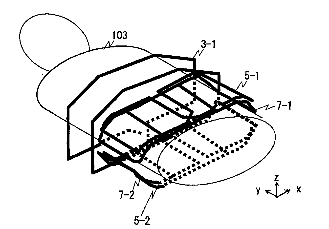
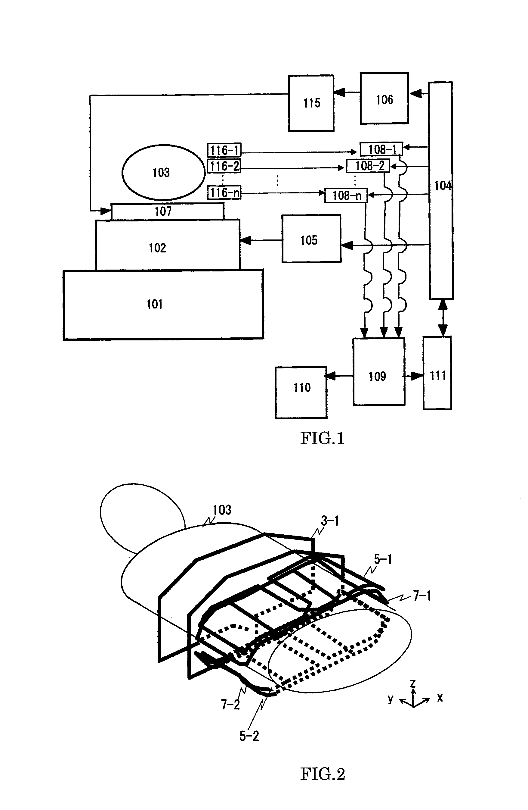
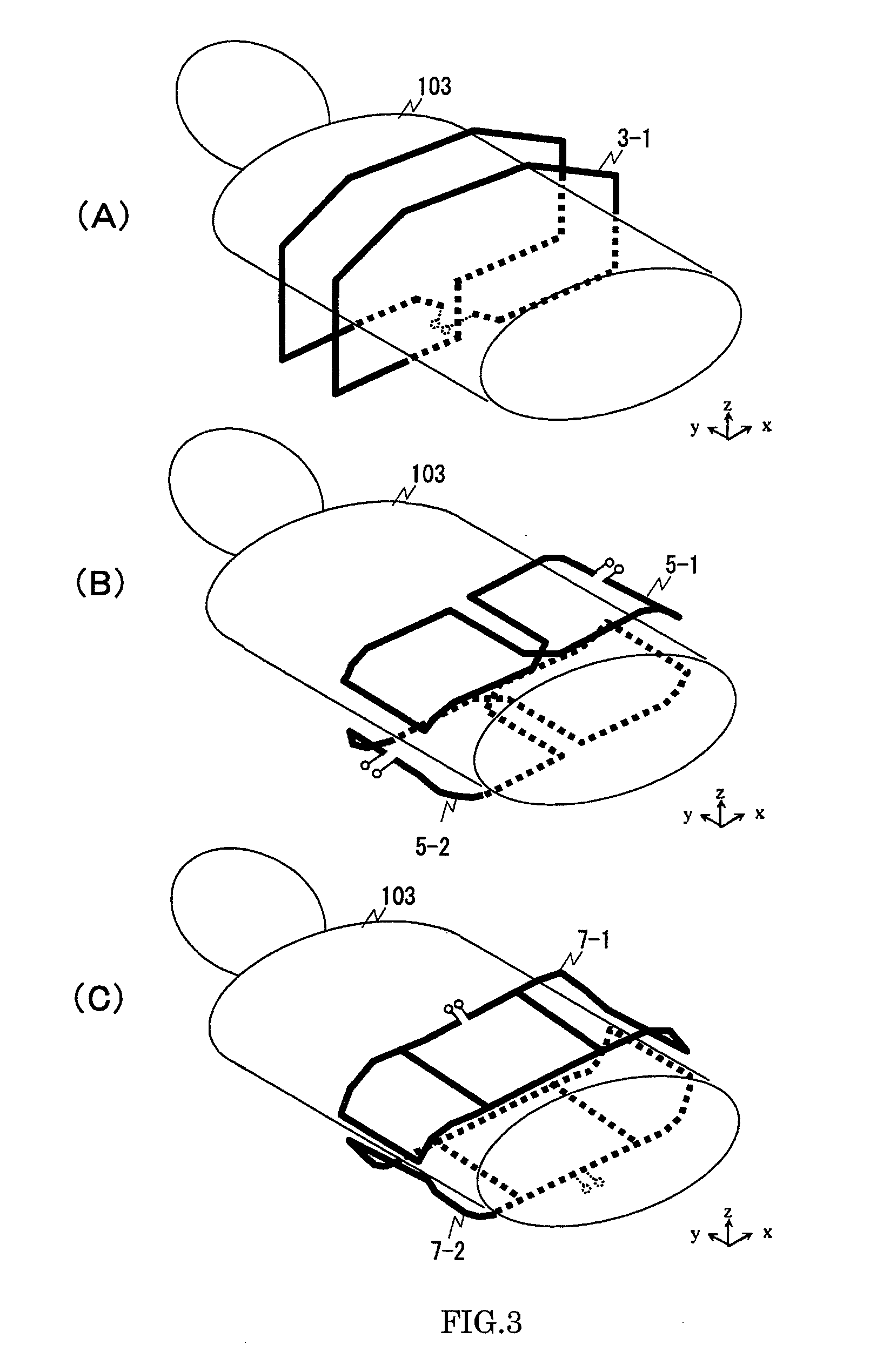
[0067]Hereinafter, an embodiment of the present invention will be explained with reference to the accompanying drawings. FIG. 1 is a block diagram showing an overall structure of a vertical magnetic field type MRI apparatus to which the present invention is applied. FIG. 29 is an external view of the apparatus. This MRI apparatus is provided with a magnet 101 that generates a static magnetic field in the vertical direction (hereinafter in the present invention, an explanation will be made assuming the direction of the static magnetic field as “z-direction”), a gradient field coil 102 that generates a magnetic field gradient, a test object (a subject to be tested) 103, a transmitter coil 107 that generates an RF pulse to be applied to a human body, for instance, a receiver coil 116 that receives a nuclear magnetic resonance (NMR) signal generated from the subject 103, a sequencer 104 that controls imaging operations, a computer 109 that subjects the NMR signal received by the receive...


PUM


Abstract

An MRI apparatus capable of selecting an optional direction as a phase encoding direction and achieving a preferable S / N, when an imaging time shortening technique is applied. A receiver coil, used as a receiver coil of a vertical magnetic field MRI apparatus, is a combination of a first coil (solenoid coil) forming a current loop around the outer circumference of a test object, second coils forming even-numbered current loops, and third coils forming odd-numbered current loops, in the direction intersecting the plane of the current loop of the first coil. The second coil and the third coil are arranged in such a manner that, as for the current loops in the array direction thereof, a position where a sensitivity of one coil is minimized approximately coincides with a position where the sensitivity of the other coil is maximized, whereby electromagnetic coupling is suppressed.

Description

TECHNICAL FIELD[0001]The present invention relates to an inspection apparatus using magnetic resonance (hereinafter, referred to as “MRI apparatus”), and more particularly, it relates to a receiver RF coil for detecting a nuclear magnetic resonance signal.BACKGROUND ART[0002]An MRI apparatus obtains a signal from a test object (a subject being tested) by nuclear magnetic resonance, and produces an image, the subject being placed in a uniform magnetic field. A field of view (FOV) is limited to a uniform magnetic field space generated from a static magnetic field magnet. However, in recent years, an imaging method has been developed, which acquires an image while moving a table with a subject placed thereon, and this enables an imaging of wide field, for example, the whole body of the subject. Imaging the wide field along with such movement of the table as described above needs shortening of imaging time, since a measuring time has to be within a range acceptable by the subject.[0003]...

Claims


Application Information

Patent Timeline
Patent Type & Authority Applications(United States)
IPC IPC(8): G01V3/00
CPCA61B5/055G01R33/34084G01R33/5611G01R33/365G01R33/3657G01R33/3415
Inventor OCHI, HISAAKITANIGUCHI, YOTAKEUCHI, HIROYUKI
Owner FUJIFILM HEALTHCARE CORP
Why Eureka
Try Eureka