Image display apparatus and method

a technology of image display and display device, which is applied in the direction of instrumentation, color television details, cathode-ray tube indicators, etc., can solve the problems of reducing the amount of light entering the observer's eyes, and reducing the brightness of the pictur

Inactive Publication Date: 2010-02-11
MITSUBISHI ELECTRIC CORP
View PDF12 Cites 107 Cited by
  • Summary
  • Abstract
  • Description
  • Claims
  • Application Information

AI Technical Summary

Benefits of technology

[0017]when the input video signal is a 3D video signal, the image display apparatus enables the light that has been modulated in the spatial modulator to be viewed stereoscopical...

Problems solved by technology

Recently, the size of the screens of display apparatus has been increasing.
The method described in Japanese Tokuhyo Publication No. 2007-531473 is problematic in that light from the light source is sequentially filtered by a color filter wheel to obtain specific colors and three-dimensional glasses having left and right lenses that transmit light of different wavelengths are used to view the spatially modulated light, so the amount of light entering the observer's eyes is cut in half in comparison with the amount emitted from the light source; consequently, the picture is darkened.
Since the response speeds of liquid crystal devices such as HTPS and LCOS devices are low, if the left-eye and right-eye images are switched at a high speed for 3D d...

Method used


Image

  • Image display apparatus and method
  • Image display apparatus and method
  • Image display apparatus and method

Examples


first embodiment

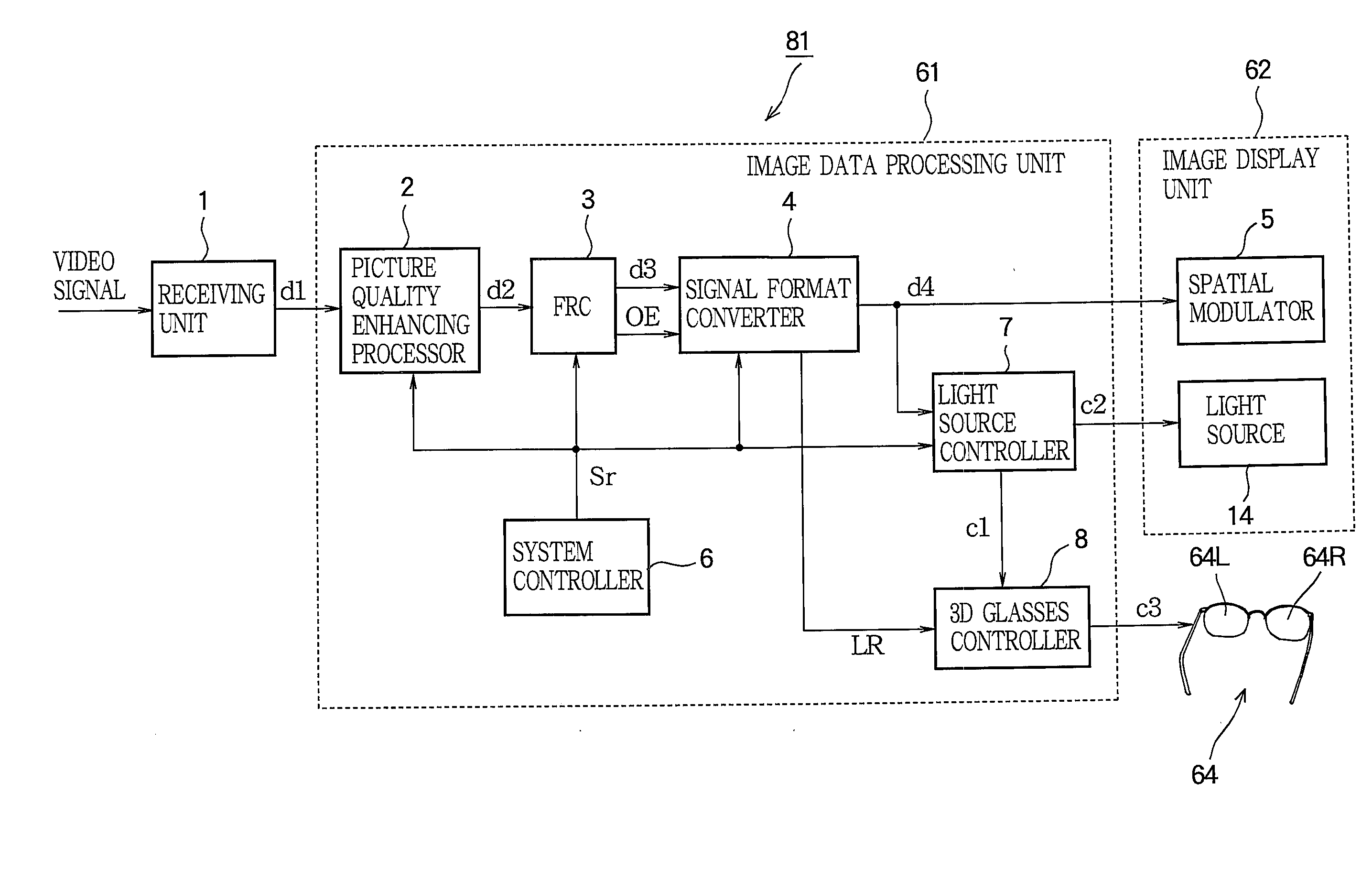
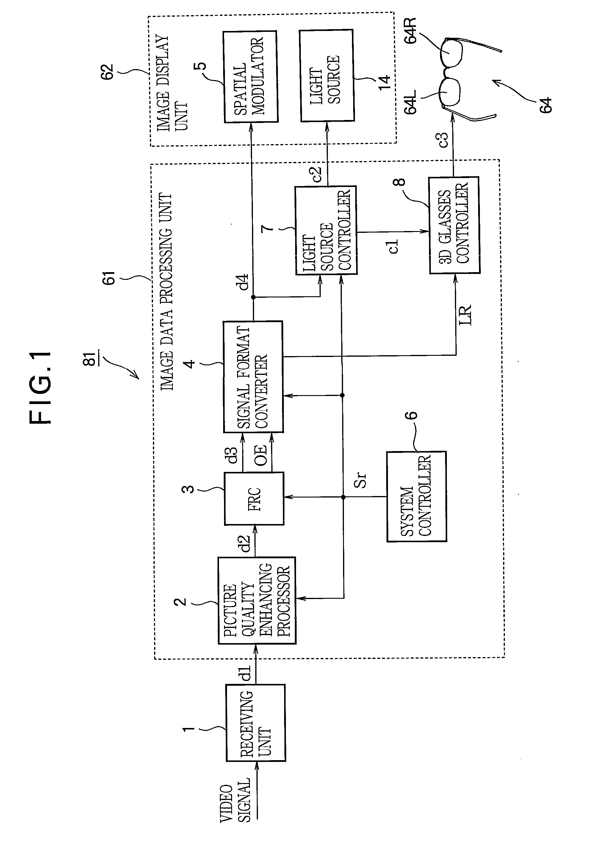
[0043]FIG. 1 is a block diagram illustrating the structure of the image display apparatus in the first embodiment of the invention. The image display apparatus 81 includes a receiving unit 1, an image data processing unit 61, and an image display unit 62.

[0044]The video signal input to the image display apparatus 81 is input to the receiving unit 1. If a composite video signal is input to the image display apparatus 81, for example, the receiving unit 1 samples the input video signal on a clock signal with a predetermined frequency, separates the luminance signal component from the chrominance signal components, and then outputs a video signal d1 including synchronizing signals, an effective image interval signal, image data signals, and other signals to the image data processing unit 61.

[0045]The image data processing unit 61 comprises a picture quality enhancing processor 2, a frame rate converter (FRC) 3, a signal format converter 4, a system controller 6, a light source controll...

second embodiment

[0118]The overall structure of the image display apparatus in the second embodiment is the same as the structure described in the first embodiment with reference to FIG. 1. The image display apparatus in the second embodiment, however, differs in the structure of the signal format converter 4.

[0119]FIG. 12 is a block diagram showing details of the signal format converter 4 in the second embodiment. The differences from the signal format converter 4 in FIG. 7 are that a frame memory controller 27 is provided in place of the frame memory controller 24 in FIG. 7 and a masking section 26 is added before the frame memory controller 27.

[0120]The video signal d3, with the rate doubled by the FRC 3, is stored into the frame memory 23 in the signal format converter 4. Although the rate depends on the number of bits of the signal, when so-called full high definition (full-HD) video having a resolution of 1920 dots×1080 lines per frame, for example, is input at a rate of 120 Hz, a transfer rat...

third embodiment

[0135]The overall structure of the image display apparatus in the third embodiment is the same as the structure described in the first embodiment with reference to FIG. 1. The signal format converter 4 in the third embodiment is generally as described in the second embodiment with reference to FIG. 12, but differs in the following respect.

[0136]In the second embodiment, when the signal format converter 4 receives a 3D video signal, a mask signal for masking the right pixels and the left pixels in alternate frames is generated and frame memory write addresses are generated from the mask signal. Therefore, the size of the video signal d4 output to the spatial modulator 5 is half the size of the video signal d1 output from the receiving unit 1. The third embodiment is a method that can be used to read and output the data written into the frame memory 23 by using the method described in the second embodiment. The reading method in the third embodiment, however, can also be used to read ...


PUM


Abstract

An image display apparatus for displaying a 3D video signal using a liquid crystal device such as an HTPS or LCOS device comprises a frame rate converter (3) that converts the input video signal to a doubled frame rate, a signal format converter (4) that converts the pixel sequence of the video signal, a light source controller (7) that outputs a light source control signal for turning the light source used for image display on and off, and a 3D glasses controller (8) that generates a glasses control signal (c3) for shutters (64R, 64L) that switch the transmission of the light to the right and left eyes of 3D glasses (64). The risk of crosstalk between the right and left images, due to device response speed is reduced, without requiring a large number of frame memories.

Description

BACKGROUND OF THE INVENTION[0001]1. Field of the Invention[0002]The present invention relates to an image display apparatus for spatially modulating light emitted from a light source and displaying the spatially modulated light on a screen, more particularly to an image display apparatus and method that enable a three-dimensional (3D) video signal to be displayed.[0003]2. Description of the Related Art[0004]Recently, the size of the screens of display apparatus has been increasing. Micro device displays, for example, have established a strong presence in the large-screen display market because their structure, in which light emitted from a light source is spatially modulated and projected through a projection lens onto a screen, facilitates increased screen area, and they take advantage of the excellent image display performance of the micro display devices used for spatial modulation, such as digital mirror devices (DMDs), high temperature polysilicon (HTPS) devices, and liquid cry...

Claims


Application Information

Patent Timeline
IPC IPC(8): H04N13/00H04N13/04
CPCG09G3/003G09G3/3406G09G2340/0435H04N13/0003H04N13/0029H04N13/004H04N7/0132H04N13/0051H04N13/0438H04N13/0497G02B27/2264H04N13/0436H04N13/0048H04N13/10H04N13/139H04N13/156H04N13/161H04N13/167H04N13/332H04N13/339H04N13/341H04N13/398G02B30/24
Inventor NAGASE, AKIHIROYAMAMURO, TAKAHIKOOKAZAKI, KOUJI
Owner MITSUBISHI ELECTRIC CORP
Why Eureka
Try Eureka