Photoacoustic microcantilevers

a technology of photoacoustic cantilevers and cantilevers, applied in the direction of instruments, specific gravity measurement, optical radiation measurement, etc., can solve the problems of difficult detection of pressure/sound waves, local heating and sound waves, and reduce the range and sensitivity of producing a photoacoustic spectrum

Inactive Publication Date: 2010-02-11
UT BATTELLE LLC +1
View PDF46 Cites 25 Cited by
  • Summary
  • Abstract
  • Description
  • Claims
  • Application Information

AI Technical Summary

Problems solved by technology

The absorption may result in local heating and a pressure / sound wave.
In an open environment, it may be difficult to detect these waves.
The waves may spread and stretch their energy outward and they may be exposed to environmental noise, which may reduce the range and sensitivity for producing a photoacoustic spectrum.
Rejection may decrease the photoacoustic intensity and absorption may increase the intensity, both of which in turn affect the vibration of the cantilever.
Any bending of the cantilever may result in changes in carrier mobility and changes in the drain current.

Method used


Image

  • Photoacoustic microcantilevers
  • Photoacoustic microcantilevers
  • Photoacoustic microcantilevers

Examples


Embodiment Construction

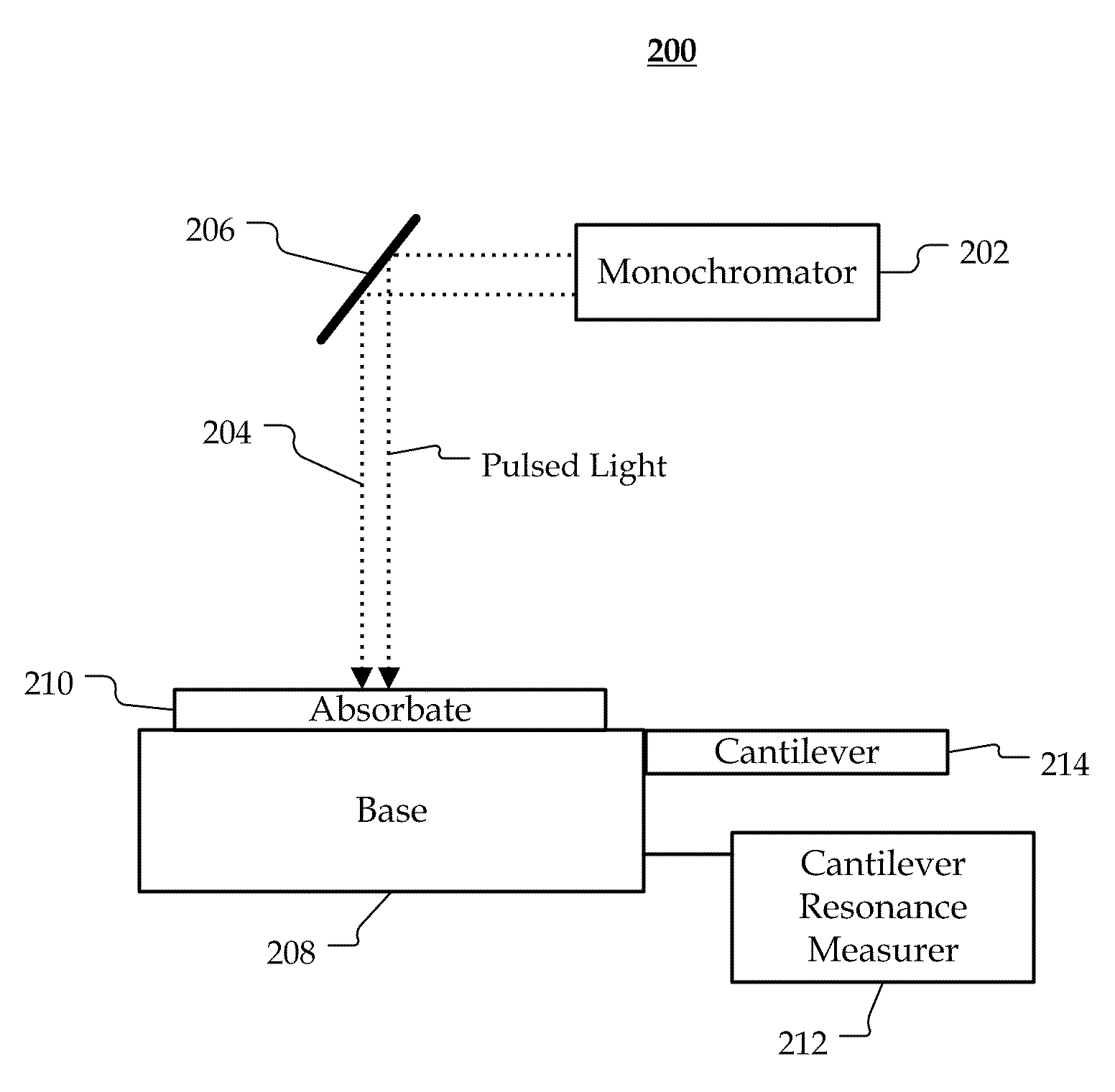
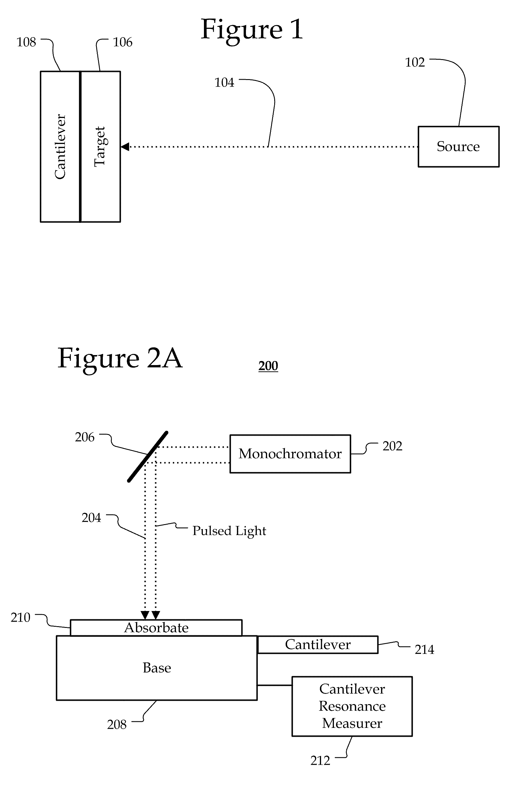
[0014]A system generates a photoacoustic spectrum using a cantilever. A source may emit a beam to a target and a cantilever measures the generated signals. The target may be a material, residue, or molecule that is located adjacent to, disposed on, or coated on a base, such as a silicon substrate with an incident surface. The cantilever may be coupled to the base to measure the reaction resulting from the beam interacting with the target at the incident surface. By emitting a chopped / pulsed light beam to the target, it may be possible to determine the target's optical absorbance by monitoring the intensity of photoacoustic vibration produced by the light with the cantilever at different wavelengths. As the wavelength of light is changed, the target may absorb or reject each optical frequency. Rejection may decrease the photoacoustic intensity and absorption may increase the intensity, both of which in turn affect the vibration of the cantilever. Accordingly, an identifying spectrum ...


PUM

PropertyMeasurementUnit
lengthaaaaaaaaaa
thicknessaaaaaaaaaa
thicknessaaaaaaaaaa

Abstract

A system generates a photoacoustic spectrum in an open or closed environment with reduced noise. A source focuses a beam on a target substance disposed on a base. The base supports a cantilever that measures acoustic waves generated as light is absorbed by the target substance. By focusing a chopped / pulsed light beam on the target substance, a range of optical absorbance may be measured as the wavelength of light changes. An identifying spectrum of the target may detected by monitoring the vibration intensity variation of the cantilever as a function of illuminating wavelength or color.

Description

PRIORITY CLAIM[0001]This application is a continuation-in-part to U.S. application Ser. No. 12 / 189,652, entitled “PHOTOACOUSTIC POINT SPECTROSCOPY,” (Atty. Dkt. 13489 / 12, 2137) filed on Aug. 11, 2008, now U.S. Pat. No. ______. This application is also a continuation-in-part to U.S. application Ser. No. 12 / 189,663, entitled “REVERSE PHOTOACOUSTIC STANDOFF SPECTROSCOPY,” (Atty. Dkt. 13489 / 28, 2138) filed on Aug. 11, 2008, now U.S. Pat. No. ______. Both of these applications are hereby incorporated by reference.STATEMENT REGARDING FEDERALLY SPONSORED RESEARCH[0002]This invention was made with government support under Contract No. DE-AC05-00OR22725 awarded by the U.S. Department of Energy. The government has certain rights in the invention.BACKGROUND[0003]Photoacoustic spectroscopy (PAS) may utilize the photoacoustic effect. The photoacoustic effect may include a conversion between light and acoustic waves due to absorption and localized thermal excitation. Light may be absorbed and tra...

Claims


Application Information

Patent Timeline
Patent Type & Authority Applications(United States)
IPC IPC(8): G01N21/00
CPCG01N29/2418G01N21/1702
Inventor THUNDAT, THOMAS G.VAN NESTE, CHARLES W.BROWN, GILBERT M.SENESAC, LAWRENCE R.
Owner UT BATTELLE LLC
Why Eureka
Try Eureka