Single-axis sensors on flexible backbone

a flexible backbone and single-axis technology, applied in the field can solve the problems of impeded probe navigation and measurement, and achieve the effect of reducing the number of invasive medical devices

Active Publication Date: 2010-02-11
BIOSENSE WEBSTER INC
View PDF12 Cites 68 Cited by
  • Summary
  • Abstract
  • Description
  • Claims
  • Application Information

AI Technical Summary

Benefits of technology

[0012]As noted in the above-described applications, it is often useful to obtain position measurements from sensors at multiple locations along the length of a catheter or other probe. In many cases, however, the navigation of the probe and measurements are impeded by the size of the position-sensing coils and the need to accommodate the coils in the very part of the probe whose location is to be sensed.

Problems solved by technology

In many cases, however, the navigation of the probe and measurements are impeded by the size of the position-sensing coils and the need to accommodate the coils in the very part of the probe whose location is to be sensed.

Method used


Image

  • Single-axis sensors on flexible backbone
  • Single-axis sensors on flexible backbone
  • Single-axis sensors on flexible backbone

Examples


embodiment 1

Alternate Embodiment 1

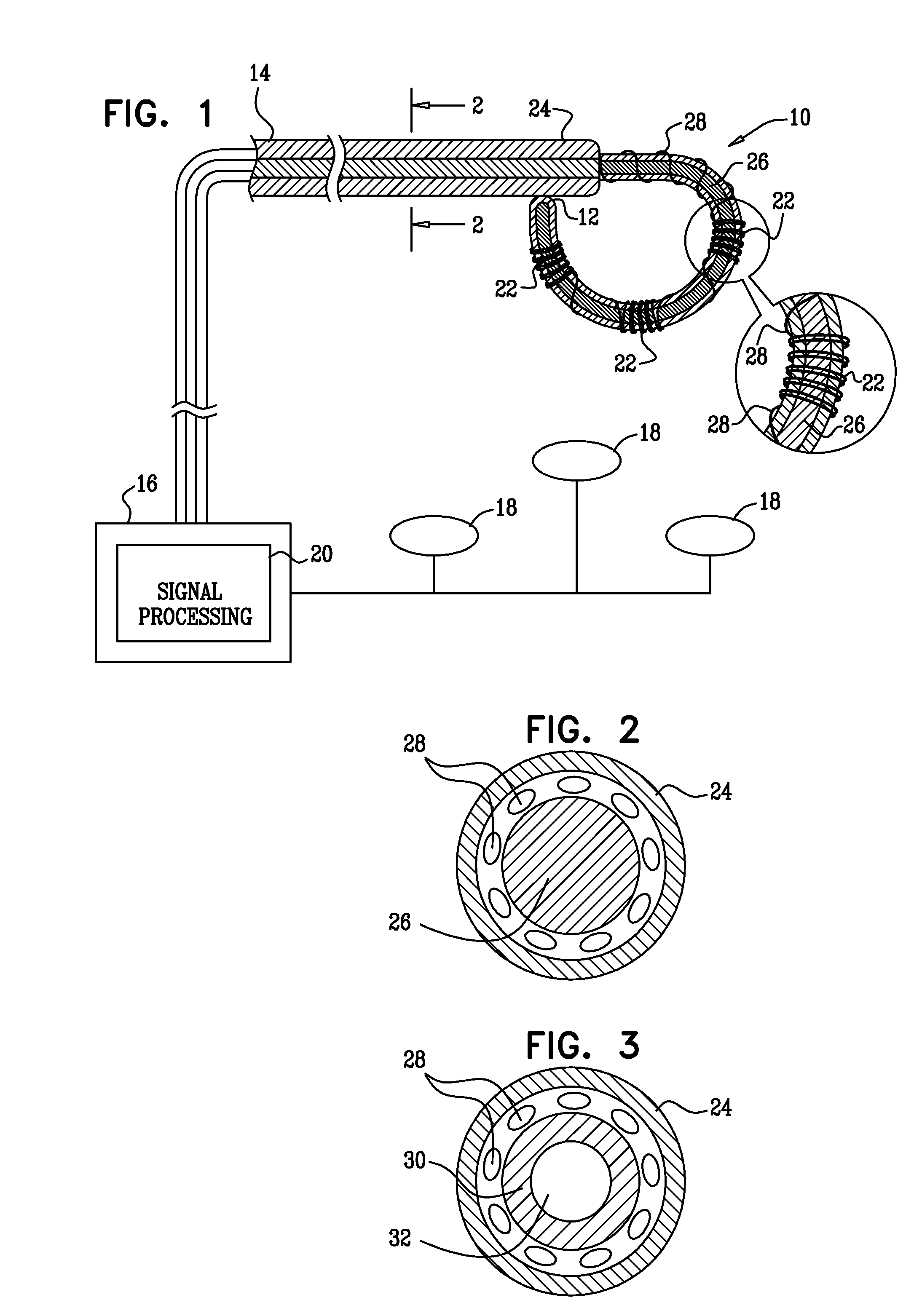
[0054]Reference is now made to FIG. 3, which is a cross sectional view through a catheter in accordance with an alternate embodiment of the invention. In this embodiment, the backbone is a hollow tube, comprising a shell 30, and a central lumen 32 that serves as a working channel for the catheter.

embodiment 2

Alternate Embodiment 2

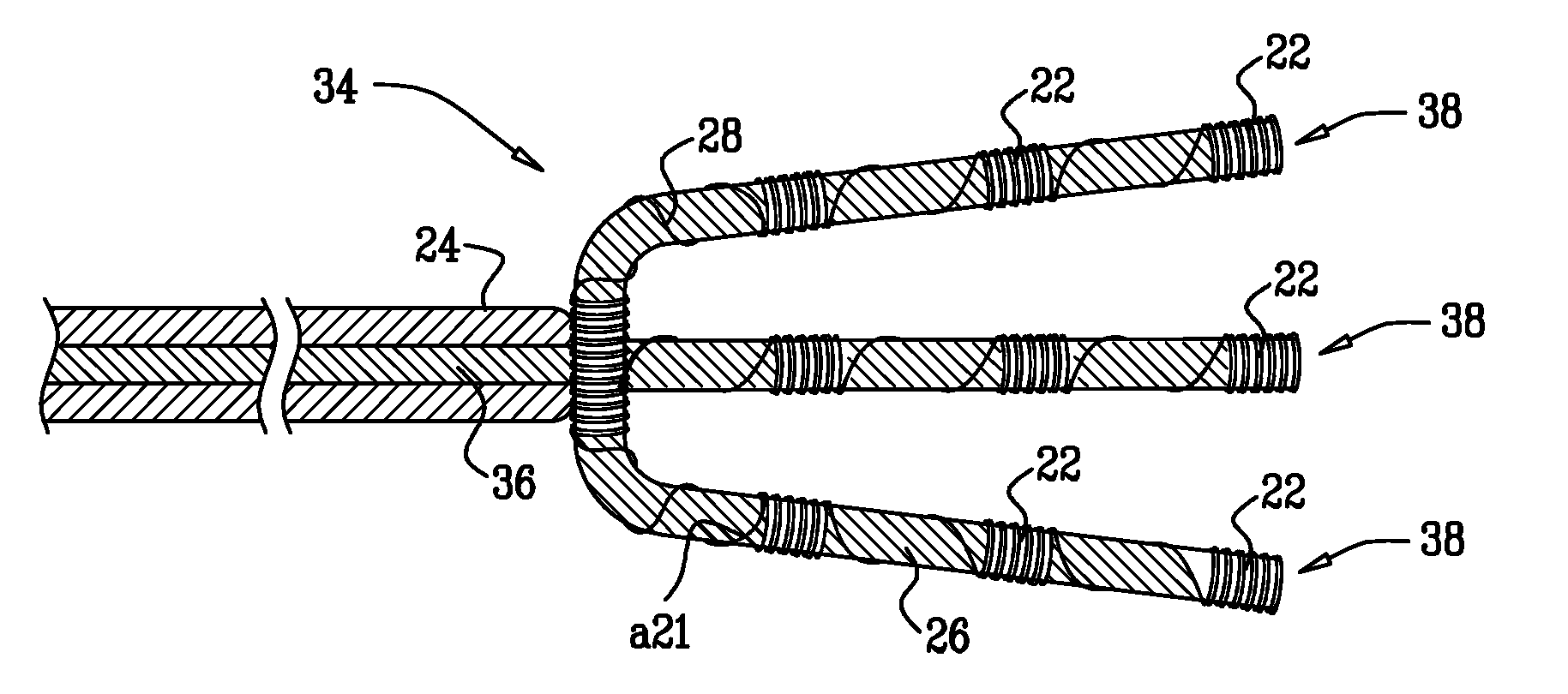
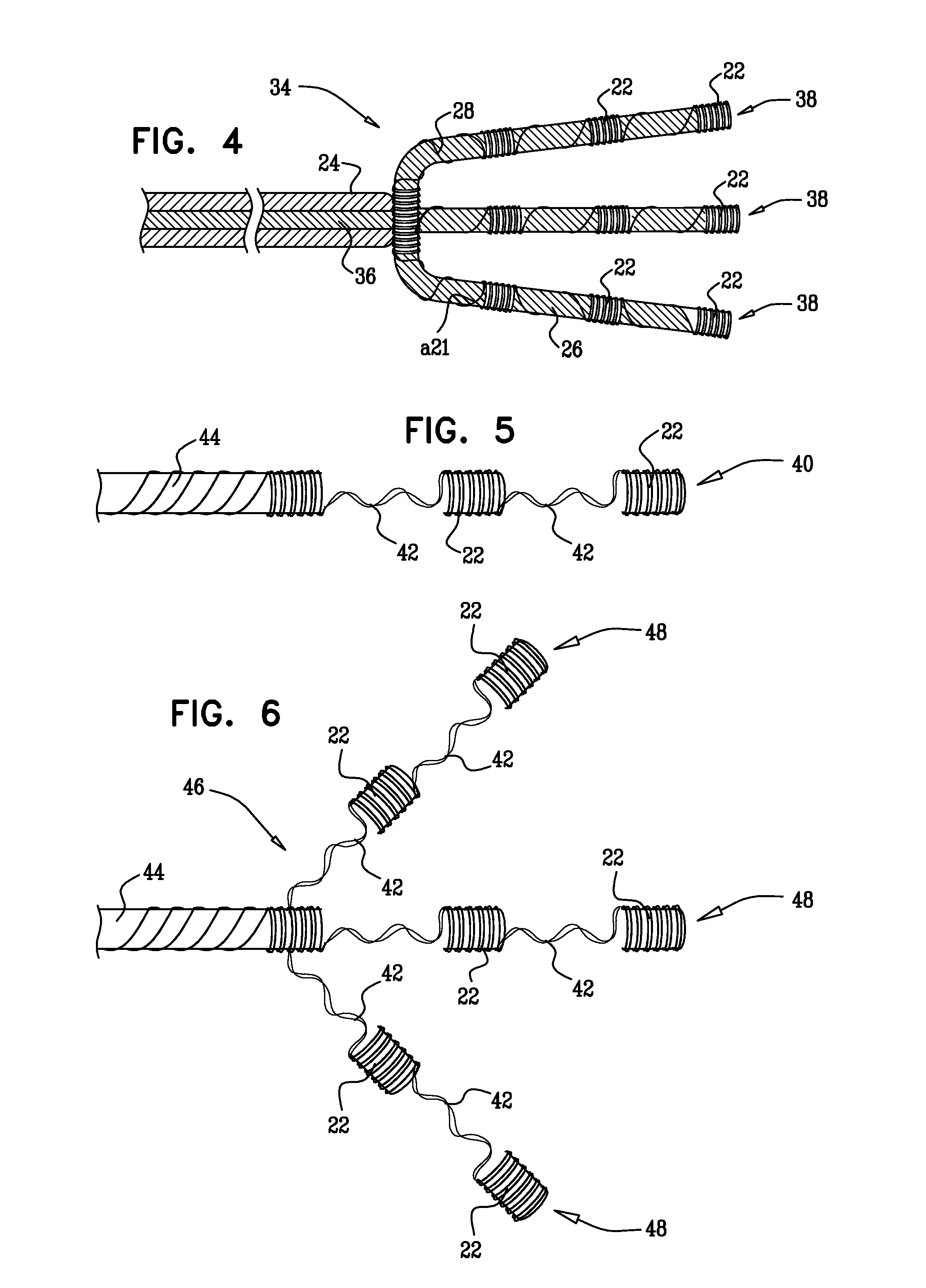
[0055]Reference is now made to FIG. 4, which illustrates the distal portion of a catheter 34 in accordance with an alternate embodiment of the invention. Like the catheter 10 (FIG. 1), the catheter 34 has a backbone 36, which divides into a plurality of branches 38, each having the same construction as described with respect in the single-branched embodiment of FIG. 1. When suitable electrodes (not shown) are incorporated into the catheter 34, the provision of a large array of coils 22 on multiple branches enables contact mapping to be accomplished quickly, with a high resolution of location information. For example, endocardial surface mapping using the coils 22 on the branches 38 allows rapid identification of an area of interest in which the earliest site of electrical activation can be precisely determined. The branches 38 are constructed so as to be flexible and soft, thus assuring atraumatic contact with target tissue.

embodiment 3

Alternate Embodiment 3

[0056]Reference is now made to FIG. 5, which illustrates the distal portion of a catheter 40 in accordance with an alternate embodiment of the invention. The distal portion of the catheter 40 is provided with a plurality of coils 22, as in the first embodiment. However, instead of a backbone, the coils 22 are supported by twisted wire pairs 42, which are sturdy enough to support the coils 22, yet flexible. Like the catheter 10 (FIG. 1), the catheter 40 is bend responsive. The wire pairs 42 connect the coils 22 with a proximal segment 44 of the catheter 40 may be constructed of a shape memory alloy, such as nickel-titanium. Alternatively, other materials, such as cobalt chromium, and annealed stainless steel, may be used.


PUM

PropertyMeasurementUnit
diameteraaaaaaaaaa
diameteraaaaaaaaaa
diameteraaaaaaaaaa

Abstract

An apparatus includes a narrow elongate probe is adapted for insertion into the body of a living subject. The probe may be flexible and has a plurality of sensors consisting of single coils of very fine wire wound about a backbone of the probe, which transmit signals proximally via fine connecting wires to a position processor. The position processor analyzes the signals to determine position coordinates at multiple points along the length of the probe.

Description

BACKGROUND OF THE INVENTION[0001]1. Field of the Invention[0002]This invention relates to invasive medical devices. More particularly this invention relates to localization of invasive medical probes within the body.[0003]2. Description of the Related Art[0004]Probes, such as catheters, which are suitable for various medical procedures and internal imaging, are now common. Such probes include angioplasty catheters, catheters with laser, electrical or cryoablation characteristics, catheters having ultrasound imaging heads, probes used for nearly incisionless surgery or diagnosis, and endoscopes.[0005]Where such probes are used for treatment, the probes must be carefully positioned in relation to the body structure. In one application, cardiac catheters comprising electrophysiological sensors are known for mapping the electrical activity of the heart. Typically, time-varying electrical potentials in the endocardium are sensed and recorded as a function of position inside the heart, an...

Claims


Application Information

Patent Timeline
Patent Type & Authority Applications(United States)
IPC IPC(8): A61B5/103A61B5/04
CPCA61B19/5244A61B2019/5251Y10T29/4902A61B5/042A61B2019/5272A61B2034/2072A61B34/20A61B2034/2051B32B1/00A61B5/062A61B5/065A61M25/0127A61B5/283A61B5/6859G01R33/285G01R33/34084A61M2025/0166G01R33/287
Inventor GOVARI, ASSAFALTMANN, ANDRES CLAUDIOMAFFRE, JENNIFERESGUERRA, MARIBETH
Owner BIOSENSE WEBSTER INC
Why Eureka
Try Eureka