Methods and systems for increasing the bending stiffness and constraining the spreading of a spinal segment

a technology of bending stiffness and spinal segment, applied in the field of methods, can solve problems such as limited movement range, and achieve the effects of reducing the risk of injury, and increasing the bending stiffness

Inactive Publication Date: 2010-02-11
SIMPIRICA SPINE
View PDF106 Cites 103 Cited by
  • Summary
  • Abstract
  • Description
  • Claims
  • Application Information

AI Technical Summary

Benefits of technology

[0031]The relative increase in bending stiffness afforded by the constraining structures of the present invention is advantageous because it allows the constraining structure to cause the treated segment to resist flexion sufficiently to relieve the underlying pain or instability with a reduced risk of injury from excessive force. In particular, the preferred bending stiffness ranges set forth above provide sufficient constraint to effect a significant change in flexion in the typical patient while allowing a significant safety margin to avoid the risk of injury. The bending stiffness provided by the constraints of the present invention will limit the separation of the spinous processes on the treated spinal segment which is desirable both to reduce flexion-related pain and spinal instability.
[0032]The resistance to flexion provided by the elastic constraints of the present invention may reduce the angular range-of-motion (ROM) relative to the angular ROM in the absence of constraint. Angular ROM is the change in angle between the inferior end plate of the superior vertebral body of the treated segment and the superior endplate of the inferior vertebral body of the treated segment when the segment undergoes flexion. Thus, the treatments afforded by the elastic constraints of the present invention will provide a relatively low angular ROM for the treated segment, but typically a ROM higher than that of a fused segment.
[0033]While the constraint structures of the present invention will limit flexion, it is equally important to note that in contrast to spinal fusion and immobilizing spinal spacers, the methods and devices of the present invention will allow a controlled degree of flexion to take place. Typically, the methods and devices of the present invention will allow a degree of flexion which is equal to at least about 20% of the flexion that would be observed in the absence of constraint, more typically being at least about 33%. By reducing but not eliminating flexion, problems associated with fusion, such as increased pain, vertebral degeneration, instability at adjacent segments, and the like, may be overcome.
[0034]The constraint structures of the present invention will act to restore the stiffness of a spinal segment which is “lax” relative to adjacent segments. Often a patient with flexion-related pain or instability suffers from a particular looseness or laxity at the painful segment. When the patient bends forward or sits down, the painful, lax segment will preferentially flex relative to the stiffer adjacent segments. By adjusting the length, position, or other feature of the devices of the present invention so that constraint structure is taut over the spinous processes when the spinal segment is in its neutral position, the stiffness of the treated segment can be “normalized” immediately as the patient begins to impart flexion to the spine. Thus, premature and / or excessive flexion of the target spinal segment can be inhibited or eliminated.
[0035]The protocols and apparatus of the present invention allow for individualization of treatment. Compliance members with different stiffnesses, elongations (lengths of travel), placement location in the anterior posterior direction along the spinous processes and other characteristics can be selected for particular patients based on their condition. For example, patients suffering from a severe loss of stiffness in the target spinal segment(s) may be treated with devices that provide more elastic resistance. Conversely, patients with only a minimal loss of natural segmental stiffness can be treated with devices that provide less elastic resistance. Similarly, bigger patients may benefit from compliance members having a greater maximum elongation, while smaller patients may benefit from compliance members having a shorter maximum elongation.
[0036]For some patients, particularly those having spinal segments which are very lax, having lost most or all of their natural segmental stiffness, the present invention can provide for “pre-tensioning” of the constraining structure. As described above, one way to accomplish this is by shortening the constraining structure such that a small amount of tension is held by the constraining structure when the spine is in the neutral or slightly extended initial position. Alternatively, pre-tensioned compliance elements can be provided to pre-tension the constraining structure without changing its length. The tension or compression elements utilized in the compliance members of the present invention, such as coil springs, elastomeric bodies, and the like, will typically present little or no elastic resistance when they are first deformed. Thus, there will be some degree of elongation of the compliance members prior to the spinal segment receiving a therapeutic resistance. To provide a more immediate relief, the tension or compression members may be pre-tensioned to have an initial static resistive force which must be overcome to initiate deformation. In this way, a constrained spinal segment will not begin to flex at the instant the patient begins to flex her or his spine which is an advantage when treating lax spinal segments. Certain specific embodiments for achieving such pre-tensioning are described in detail below.

Problems solved by technology

For example, the range of movement may be limited and the bending stiffness increased using a device having an elastic component together with stops or other mechanical constraints which provide a “hard stop” to prevent extension of the device beyond the allowed limited spreading distance of the spinous processes.

Method used


Image

  • Methods and systems for increasing the bending stiffness and constraining the spreading of a spinal segment
  • Methods and systems for increasing the bending stiffness and constraining the spreading of a spinal segment
  • Methods and systems for increasing the bending stiffness and constraining the spreading of a spinal segment

Examples


Embodiment Construction

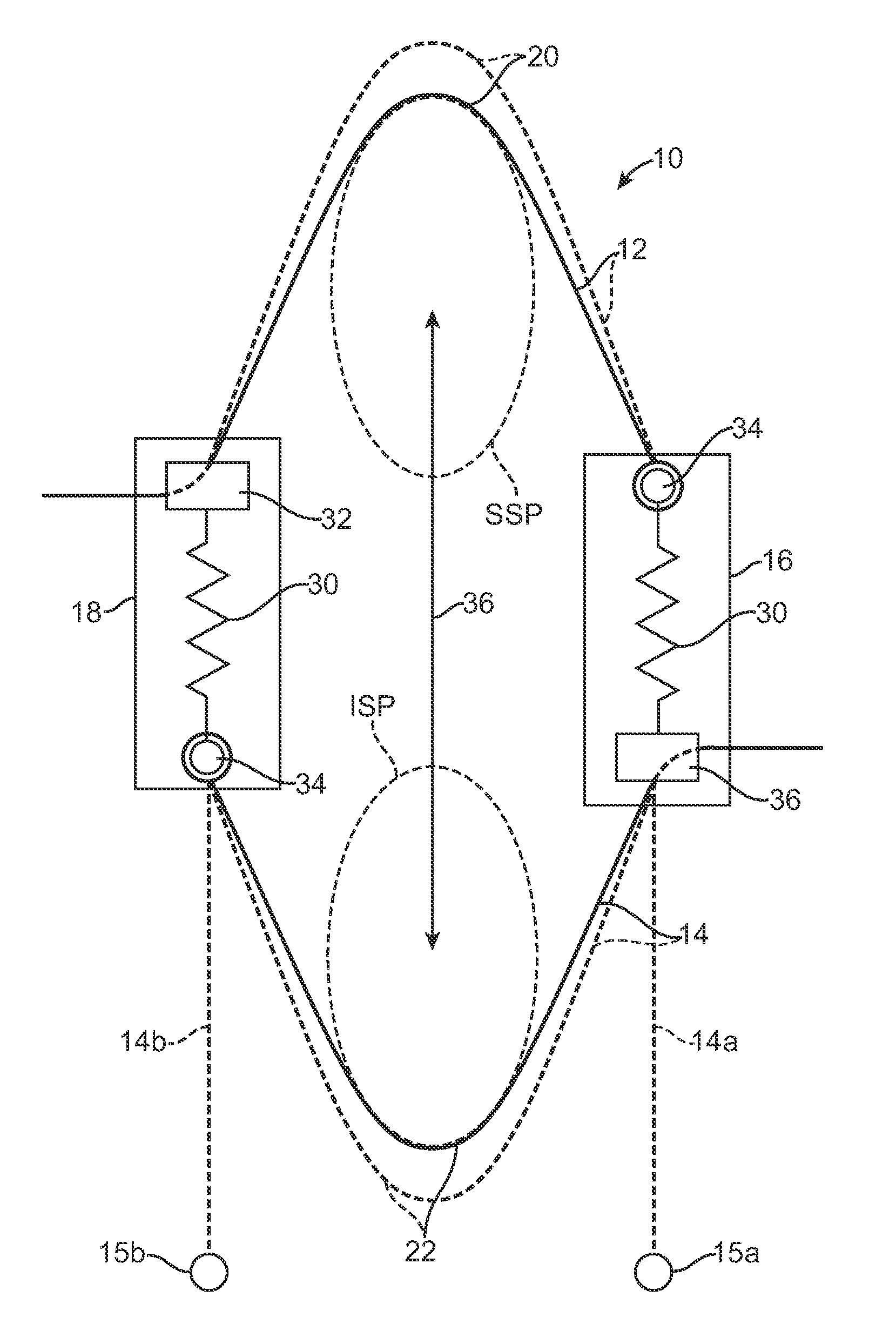
[0061]Exemplary spinous process constraints according to the present invention are illustrated schematically in FIG. 3. The systems 10 comprise a superior tether structure 12, and inferior tether structure 14, and right compliance member 16 and a left compliance member 18. The superior tether structure 12 will typically be a continuous band, cable, strap, cord, or other structure which extends between the two compliance members and provides a saddle region 20 which is adapted to lie over and conform to a superior surface of a superior spinous process SSP as described in more detail in the related prior applications which have been incorporated herein by reference. The inferior tether structure 14 will typically comprise a band, cable, or the like which is constructed similarly if not identically to the superior tether structure 12 and has a saddle region 22 adapted to lie over and conform to an inferior surface of an inferior spinous process 22. In certain instances, however, the in...


PUM


Abstract

A system for restricting spinal flexion includes superior and inferior tether structures joined by a pair of compliance members. Compliance members comprise tension members which apply a relatively low elastic tension on the tether structures. By placing the tether structures on or over adjacent spinous processes, flexion of a spinal segment can be controlled in order to reduce pain.

Description

CROSS-REFERENCES TO RELATED APPLICATIONS[0001]This application is a continuation-in-part of application Ser. No. 12 / 106,103 (Attorney Docket No. 026398-000410US), filed on Apr. 18, 2008, which claims the benefit of provisional application 60 / 936,897, (Attorney Docket No. 026398-000400US), filed on Jun. 22, 2007, the full disclosures of which are incorporated herein by reference.[0002]The present invention is related to but does not claim priority from application Ser. No. 11 / 076,469, filed on Mar. 9, 2005, now U.S. Pat. No. 7,458,981, which claimed the benefit of prior provisional application 60 / 551,235, filed on Mar. 9, 2004; application Ser. No. 11 / 777,366 (Attorney Docket No. 026398-000110US); filed on Jul. 13, 2007; application Ser. No. 11 / 827,980 (Attorney Docket No. 026398-000120US); filed on Jul. 13, 2007; PCT application no. US 2007 / 081815 (Attorney Docket No. 026398-000130PC); filed on Oct. 18, 2007; PCT application no. US 2007 / 081822 (Attorney Docket No. 026398-000140PC); ...

Claims


Application Information

Patent Timeline
Patent Type & Authority Applications(United States)
IPC IPC(8): A61B17/70A61B17/58A61B17/88
CPCA61B17/7053A61B17/7067A61B17/7068A61B17/842A61B17/7062A61B17/82A61B2019/464A61B2090/064
Inventor FIELDING, LOUISBENNETT, IANKOTHARI, MANISHALAMIN, TODDMALANDAIN, HUGUESLITHERLAND, CRAIGCAHILL, COLIN
Owner SIMPIRICA SPINE
Why Eureka
Try Eureka