
Autoloop system and method of operation

a technology of automatic loops and loops, applied in the direction of emergency power supply arrangements, electric programme control, program control, etc., can solve the problems of feeder reclosers on non-faulted branch circuits to trip, customers on unaffected branch circuits to experience one momentary interruption of electrical power

Active Publication Date: 2010-02-11
CONSOL EDISON OF NEW YORK
View PDF27 Cites 28 Cited by
  • Summary
  • Abstract
  • Description
  • Claims
  • Application Information

AI Technical Summary

Benefits of technology

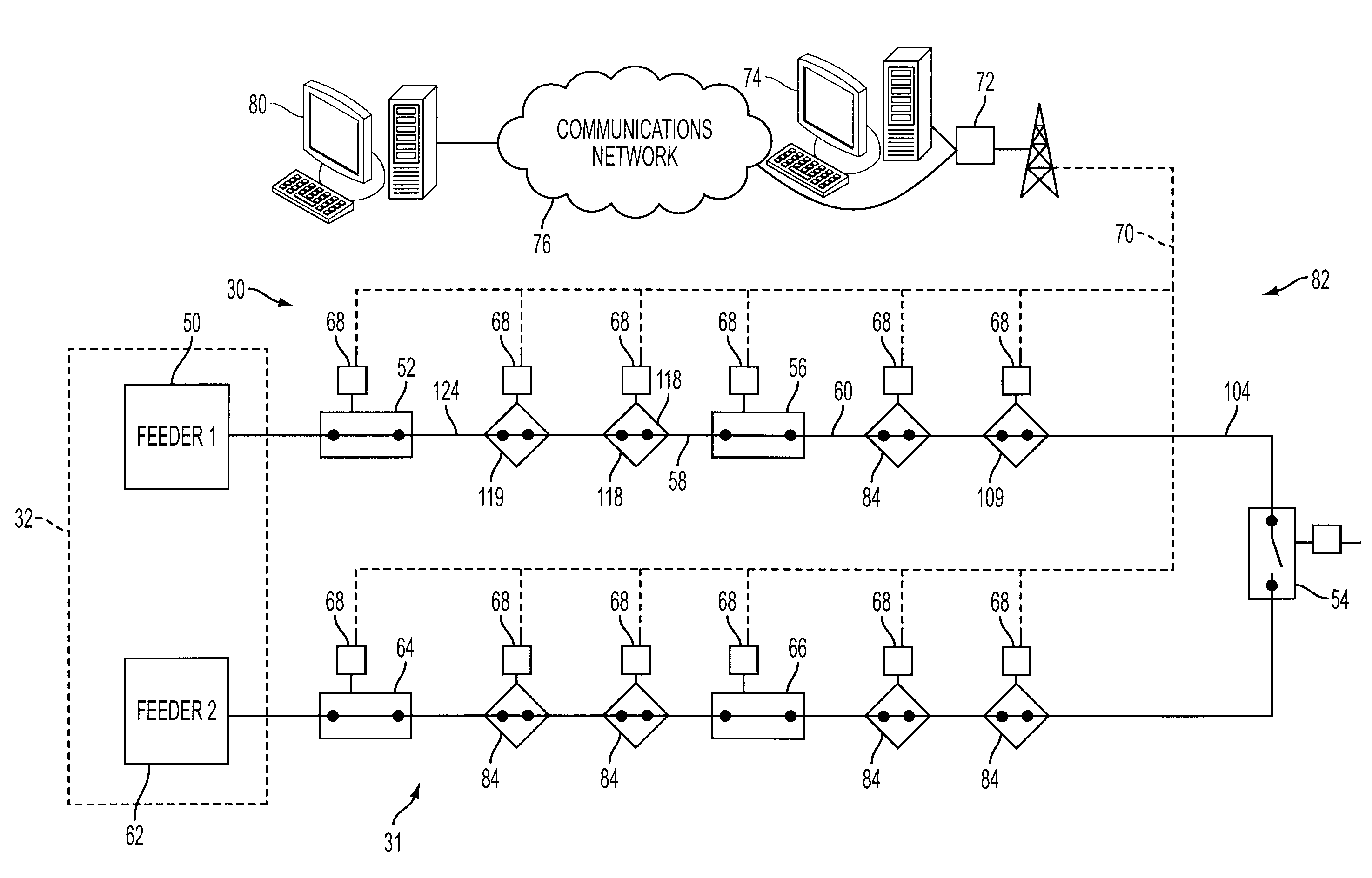
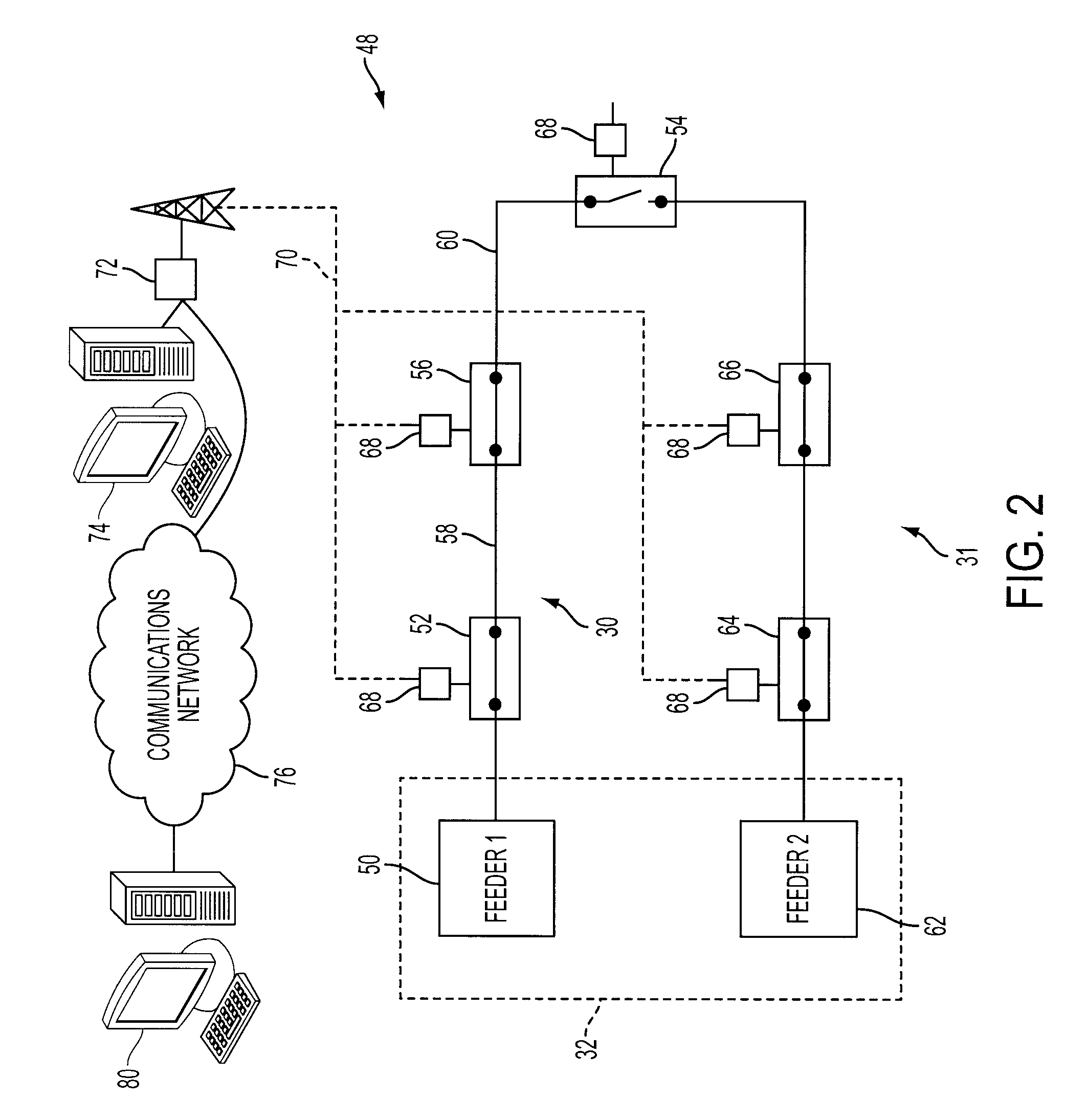
[0009]A method of operating an automatic loop system for an electrical distribution system is also provided. The method includes the step of monitoring an electrical characteristic of a first branch circuit. A change is detected in the electrical characteristic indicative of a fault condition. A first signal is transmitted to a first controller. Devices on said first branch circuit are polled for voltage and current measurements an...

Problems solved by technology

In the event of a fault between the feeder and midpoint that the feeder recloser cannot clear, the feeder recloser locks open and results in a loss of potential on the branch circuit.
However, since the fault is still present when tie recloser connects the branch circuits, the feeder recloser that protects the second or unaffected branch circuit will also detect the fault.
The detection of the fault may cause the feeder recloser on the non-faulted branch circuit to trip once on a fast trip.
Thus, the customers on the unaffected branch circuit will experience one momentary interruption in electrical power during a short period of time after the tie recloser connects the branch circuits and before the midpoint recloser near the fault trips.
The closing of the tie recloser into a fault also creates undesirable power quality issues in the branch circuits.
When the tie reclosure attempts to close into the faulted circuit, the voltage on the faulted phase sags and the unaffected phases may experience a voltage rise.

Method used


Image

  • Autoloop system and method of operation
  • Autoloop system and method of operation
  • Autoloop system and method of operation

Examples


Embodiment Construction

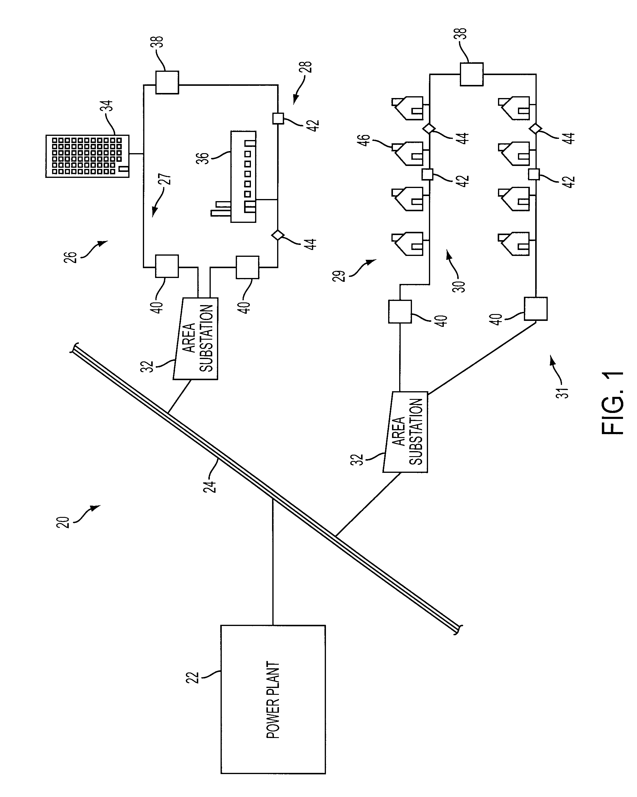
[0019]FIG. 1 illustrates an exemplary embodiment of a utility electrical distribution system 20. The utility system 20 includes one or more power plants 22 connected in parallel to a main transmission system 24. The power plants 22 may include, but are not limited to: coal, nuclear, natural gas, or incineration power plants. Additionally, the power plant 22 may include one or more hydroelectric, solar, or wind turbine power plants. It should be appreciated that additional components such as transformers, switchgear, fuses and the like (not shown) may be incorporated into the utility system 20 as needed to ensure the safe and efficient operation of the system. The utility system 20 is typically interconnected with one or more other utility networks to allow the transfer of electrical power into or out of the electrical system 20.

[0020]The main transmission system 24 typically consists of high transmission voltage power lines, anywhere from 69 KV to 500 KV for example, and associated ...


PUM


Abstract

A system and method for operating an autoloop system on a electrical distribution system is provided. The system includes a master controller that is disposed in communication with controllers associated with reclosers and switches coupled to a first and second branch circuit. The system is arranged to momentarily block the one fast tripping function of a feeder recloser in response to the detection of a fault on the other branch circuit. The system further includes means for isolating a segment on which a fault is located and restoring electrical power service to those areas upstream and downstream from the isolated segment.

Description

BACKGROUND OF THE INVENTION[0001]The present invention relates generally to automatic loop (“autoloop”) system for an electrical power distribution network and more particularly to an autoloop system that eliminates momentary power interruptions on the non-faulted portion of the electrical loop and which prevents reclosers from closing in on known faults.[0002]Electrical utilities have a number of metrics that are used to track performance and customer satisfaction. These metrics, which include the system average interruption frequency index (“SAIFI”), the customer average interruption duration index (“CAIDI”), and for some utilities, the momentary average interruption frequency index (“MAIFI”). SAIFI measures the average number of interruptions that a customer would experience during a time period, such as a year. CAIDI measures the duration of the interruption that a customer would experience, and is generally a few hours per year. MAIFI measures the number of power interruptions ...

Claims


Application Information

Patent Timeline
IPC IPC(8): G06F19/00
CPCH02H7/30H02H7/263
Inventor STERGIOU, PAUL V.HARRIS, WILLIAM J.
Owner CONSOL EDISON OF NEW YORK
Learn More