This helps you quickly interpret patents by identifying the three key elements:
Problems solved by technology
Method used
Benefits of technology
[0016]It is another aspect of the present invention to employ a cable that is made of plastic instead of a braided or solid metal cables. Preferably, such cables are lighter, more flexible and corrosion resistant than metal cables.
[0017]It is yet anothe
Problems solved by technology
Drain manipulation and control devices that employ chains and cables suffer from problems posed by corrosion, chain tangling, and rigidity issues.
These drawbacks of current devices are further compounded by the fact that they are generally inaccessible for repair.
As these devices are typically located within the tub or surrounding structure, maintenance or repair thereof is complicated and costly.
Typically, unless the original installer provided an access panel, costly removal, replacement, and repair of the stone, tile, or other material surrounding the drain is necessary.
One drawback of Kreuzer is that the cable is located on the inside of the drain pipe.
The problem with this configuration is that the cable cannot be easily adjusted to accommodate overflow assemblies of various lengths.
Providing a fixed length of cable as taught by Kreuzer does not allow
Method used
Image
Click on the blue label to locate the original text in one second.
Reading with bidirectional positioning of images and text.
Examples
Embodiment Construction
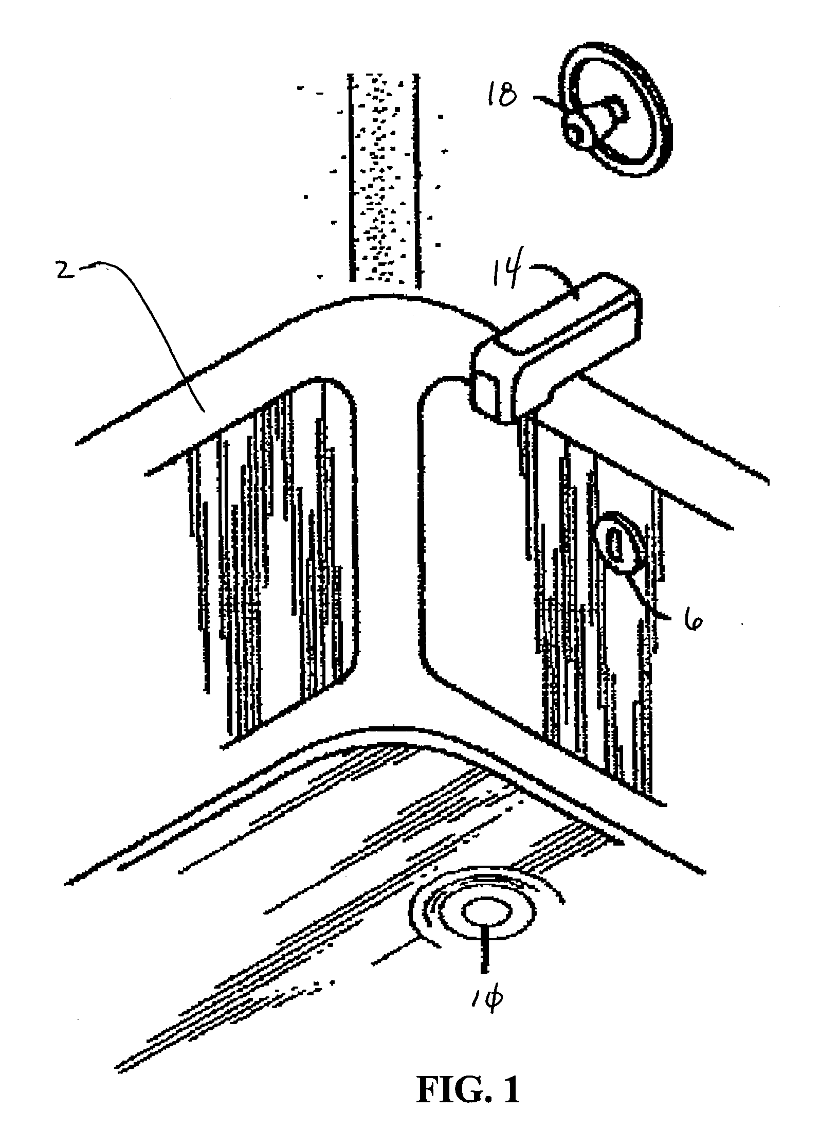
[0034]FIG. 1 shows a bathtub 2 having an overflow port 6 and a drain port 10. The bathtub 2 is filled with water by way of a water inlet 14 where a knob 18 is rotated.
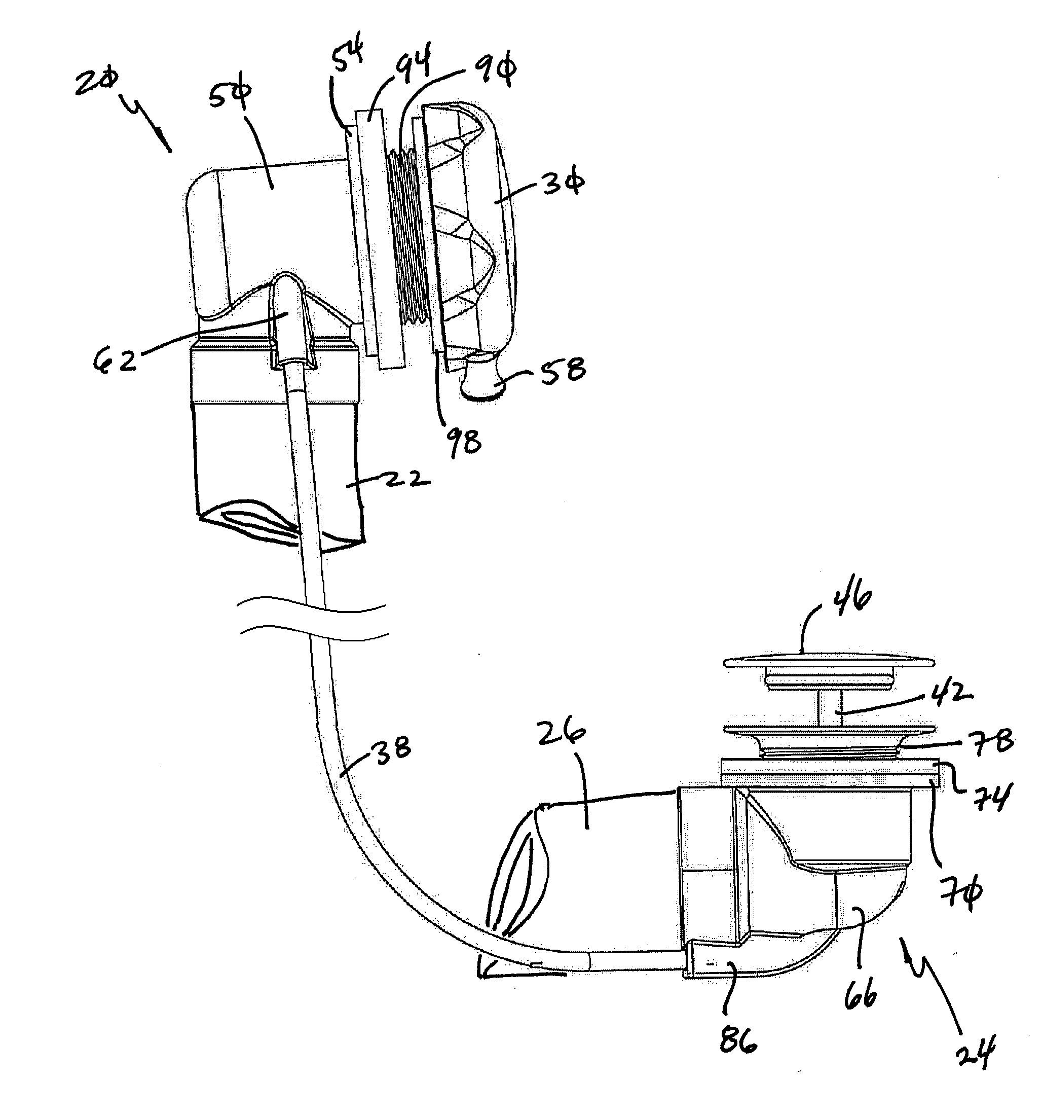
[0035]Referring now to FIGS. 2-7, one embodiment of the present invention is shown that employs an overflow assembly 20 with an overflow pipe 22 and a drain assembly 24 with a drain pipe 26. The overflow pipe 22 includes a rotatable overflow cap 30 that is associated with a cable 34 situated in a sheath 38. The cable 34 is also associated with a post 42 of the drain assembly 24 wherein selective rotation of the cap 30 moves a head 46 of the drain assembly 24 from a first position of use to a second position of use.
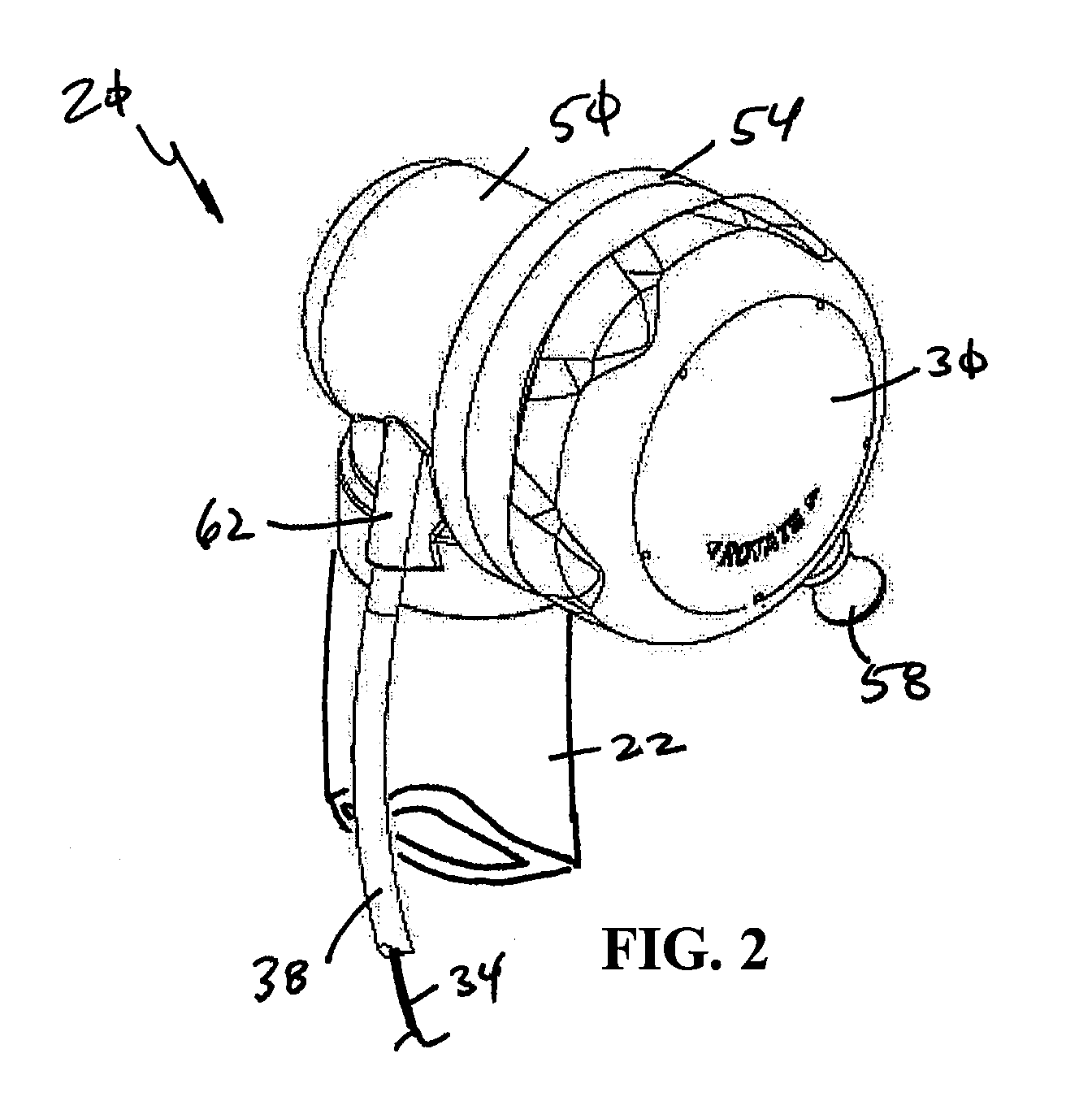
[0036]Referring now specifically to FIG. 2, the overflow assembly 20 is shown that is comprised of an overflow elbow 50 interconnected to the overflow pipe 22. The overflow elbow 50 also includes a flange 54 that is spaced from the overflow cap 30. The overflow cap 30 may also include a knob 58 positioned the...
PUM
Abstract
An improved drain actuates system that includes a cable to actuate a head or stopper of a drain. More specifically, one end of the cable is associated with the drain without additional moving parts and another end of the cable associated with an overflow cap of an overflow system wherein rotation of the overflow cap selectively moves the cable to move the head of the drain. The internal components associated with the overflow end of the cable that allow it to actuate the drain are fully accessible through the overflow port of the plumbing system.
Description
[0001]This application claims the benefit of U.S. Provisional Patent Application Ser. No. 61 / 089,692 filed Aug. 18, 2008, the entire disclosure which is incorporated by reference herein.[0002]This application also is related to various applications and patents related to overflow systems associated with bathtubs or other basins. That is, this application is related to U.S. patent application Ser. No. 09 / 593,724 filed Jun. 13, 2000, U.S. Patent Application Publication Nos. 2004 / 0068793, filed Sep. 30, 2003, 2004 / 0117907, filed Dec. 10, 2003, 2004 / 0111797, filed Dec. 17, 2003, 2008 / 0235866, filed Mar. 28, 2008 and 2004 / 0103474 filed Nov. 25, 2003. In addition, this application is related to U.S. Pat. No. 6,691,411, filed Sep. 17, 2001, U.S. Pat. No. 6,675,406, filed Aug. 28, 2002, U.S. Pat. No. 6,637,050, filed Aug. 16, 2002, U.S. Pat. No. 7,127,752, filed Dec. 17, 2003 and U.S. Pat. No. 5,890,241, filed Feb. 4, 1998. The entire disclosures of which are incorporated by reference herei...
Claims
Application Information
Patent Timeline
Application Date:The date an application was filed.
Publication Date:The date a patent or application was officially published.
First Publication Date:The earliest publication date of a patent with the same application number.
Issue Date:Publication date of the patent grant document.
PCT Entry Date:The Entry date of PCT National Phase.
Estimated Expiry Date:The statutory expiry date of a patent right according to the Patent Law, and it is the longest term of protection that the patent right can achieve without the termination of the patent right due to other reasons(Term extension factor has been taken into account ).
Invalid Date:Actual expiry date is based on effective date or publication date of legal transaction data of invalid patent.
IPC IPC(8): E03C1/232
CPCE03C1/232E03C1/2304
Inventor BALL, WILLIAM T.PILARCZYK, ERICHOGAN, KEVIN T.RIESCO, CARL F.