Internal combustion engine control for improved fuel efficiency

a technology for internal combustion engines and fuel efficiency, applied in the direction of electric control, ignition automatic control, instruments, etc., can solve the problems of engine operation under conditions well below their optimal thermodynamic, more power (and often far more power) than desired or appropriate, and the effect of optimizing the thermodynamic efficiency, smoothing and/or more precise control of the torque output, and reducing the probability of resonant vibration

Active Publication Date: 2010-02-18
TULA TECH INC
View PDF21 Cites 8 Cited by
  • Summary
  • Abstract
  • Description
  • Claims
  • Application Information

AI Technical Summary

Benefits of technology

[0016]In some embodiments the controller used to determine the skip fire firing pattern includes a drive pulse generator arranged to receive an input indicative of a desired engine output and to output a drive pulse signal that is synchronized with the engine speed. The drive pulse signal generally indicates when active working cycles are appropriate to deliver the desired engine output. In some implementations, the output of the drive pulse generator may directly be used to define the firing pattern. In other embodiments, a sequencer is used to define the actual firing pattern based at least in part on the drive pulse pattern. The working chamber firings may be sequenced in a manner that helps reduce undesirable vibrations of the engine.
[0018]In many operational conditions, the amount of fuel injected into the working chambers in the variable displacement mode is set to operate the working chambers at substantially their optimal thermodynamic efficiency under the current operational conditions. In some embodiments the controller may be arranged to sometimes cause injection of different amounts of fuel into the fired working chambers. Injection of the different fuel quantities can be used to provide smoother and / or more precise control of the torque outputted by the engine and / or to reduce the probability of resonant vibrations occurring during operation in the variable displacement mode and / or to enhance emission characteristics.
[0019]The described approaches can be used to significantly improve the fuel efficiency of a wide variety of internal combustion engines, including 2-stroke, 4-stroke and 6-stroke piston engines, rotary engines, hybrid engines, radial engines, etc. The approach is applicable to engines that operate in accordance with a variety of different thermodynamic cycles including an Otto cycle, a diesel cycle, a Miller cycle, an Atkins cycle, mixed cycles, etc.

Problems solved by technology

However, in engines that control the power output by using a throttle to regulate the flow of air into the cylinders (e.g., Otto cycle engines used in many passenger cars), operating at an unthrottled position (i.e., at “full throttle”) would typically result in the delivery of more power (and often far more power) than desired or appropriate.
Operating such engines at thermodynamically optimal fuel injection levels, again, would typically result in the delivery of more power than desired or appropriate.
Therefore, in most applications, standard internal combustion engines are operated under conditions well below their optimal thermodynamic efficiency a significant majority of the time.
There are a number of reasons that internal combustion engines do not operate as efficiently at partial throttle.
One of the most significant factors is that less air is provided to the cylinder at partial throttle than at full throttle which reduces the effective compression of the cylinder, which in turn reduces the thermodynamic efficiency of the cylinder.
Another very significant factor is that operating at partial throttle requires more energy to be expended to pump air into and out of the cylinders than is required when the cylinder is operating at full throttle—these losses are frequently referred to as pumping losses.
When a cylinder is “shut down”, its piston still reciprocates, however neither air nor fuel is delivered to the cylinder so the piston does not deliver any power during its power stroke.
Although the remaining cylinders tend to operate at improved efficiency, they still do not operate at their optimal efficiency the vast majority of the time because they are still not operating consistently at “full throttle.” That is, they have the same drawbacks of partial throttle operations, (e.g., lower compression, higher pumping losses) even though the scale of their inefficiencies is reduced.
Another drawback of most commercially available variable displacement engines is that they tend to kick out of the variable displacement mode very quickly when changes are made to the desired operational state of the engine.
It is believed that the reason that such variable displacement engines kick out of the variable displacement mode so quickly is due to the perceived difficulty of controlling the engine to provide substantially the same response regardless of how many cylinders are being used at any given time.
Although such designs can improve thermodynamic and fuel efficiencies, existing variable cylinder size designs tend to be relatively complicated and expensive to produce, making them impractical for widespread use in commercial vehicles.
However, the approach described in the '488 patent never achieved commercial success.
It is suspected that this was partly due to the fact that although the distribution of the skipped working strokes varied based on the load, a discrete number of different firing patterns were contemplated so the power outputted by the engine would not regularly match the desired load precisely, which would be problematic from a control and user standpoint.
In some embodiments, the firing patterns were fixed—which inherently has the risk of introducing resonant vibrations into the engine crankshaft.
However, this approach has the disadvantage of introducing bigger variations in drive energy.
In short, it appears that the approach proposed by the '488 patent was not able to control the engine operation well enough to attain commercial success.

Method used


Image

  • Internal combustion engine control for improved fuel efficiency
  • Internal combustion engine control for improved fuel efficiency
  • Internal combustion engine control for improved fuel efficiency

Examples


Embodiment Construction

[0044]The present invention relates generally to methods and arrangements for controlling the operation of internal combustion engines to improve their thermodynamic and fuel efficiencies. Various aspects of the invention relate to motorized vehicles that utilize such engine control and to engine control units suitable for implementing such control.

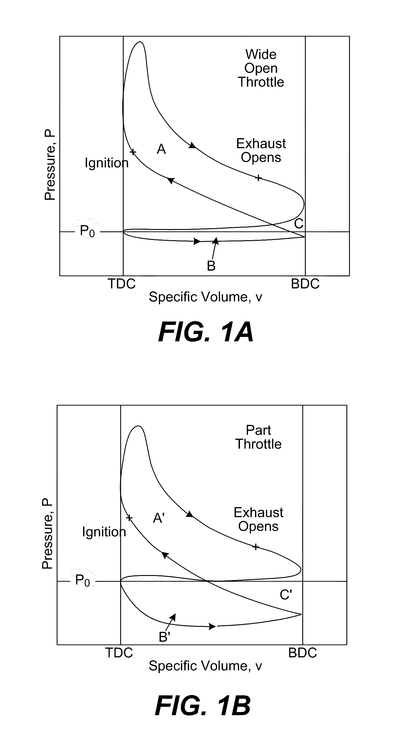
[0045]Most internal combustion engines are arranged to vary the amount of air and / or fuel that is delivered to the cylinders (or other working chambers) based on the engine output that is requested by the user or otherwise required at any given time. However, the thermodynamic efficiency of a fixed size cylinder is not the same at every air / fuel level. Rather, the thermodynamic efficiency is best when an optimal amount of air and fuel is delivered to the cylinder to achieve maximum permissible compression and optimal combustion efficiency. Since internal combustion engines need to be able to operate under a wide variety of different loads...


PUM


Abstract

A variety of methods and arrangements for improving the fuel efficiency of internal combustion engines are described. Generally, an engine is controlled to operate in a skip fire variable displacement mode. Feedback control is used to dynamically determine the working cycles to be skipped to provide a desired engine output. In some embodiments a substantially optimized amount of air and fuel is delivered to the working chambers during active working cycles so that the fired working chambers can operate at efficiencies close to their optimal efficiency. In some embodiments, the appropriate firing pattern is determined at least in part using predictive adaptive control. By way of example, sigma delta controllers work well for this purpose. In some implementations, the feedback includes feedback indicative of at least one of actual and requested working cycle firings. In some embodiments, the appropriate firings are determined on a firing opportunity by firing opportunity basis. Additionally, in some embodiments, an indicia of the current rotational speed of the engine is used as a clock input for a controller used to selectively cause the skipped working cycles to be skipped.

Description

CROSS REFERENCE TO RELATED APPLICATIONS[0001]This application is a Continuation of U.S. patent application Ser. No. 12 / 501,345 filed on Jul. 10, 2009, which is a Continuation-in-Part of U.S. patent application Ser. No. 12 / 355,725 filed Jan. 16, 2009 and further claims the priority of U.S. Provisional Patent Application Nos.: 61 / 080,192, filed Jul. 11, 2008; and 61 / 104,222, filed Oct. 9, 2008. Each of these priority applications is incorporated herein by reference and all are entitled: “INTERNAL COMBUSTION ENGINE CONTROL FOR IMPROVED FUEL EFFICIENCY.”FIELD OF THE INVENTION[0002]The present invention relates generally to internal combustion engines and to methods and arrangements for controlling internal combustion engines to operate more efficiently. Generally, selected combustion events are skipped during operation of the internal combustion engine so that other working cycles can operate at better thermodynamic efficiency.BACKGROUND OF THE INVENTION[0003]There are a wide variety of...

Claims


Application Information

Patent Timeline
Patent Type & Authority Applications(United States)
IPC IPC(8): F02P5/04F02D43/00
CPCF02D37/02F02D41/0087F02D41/1401F02D41/266Y02T10/46F02D2250/18F02D2400/02F02P5/1512F02D2200/602Y02T10/40
Inventor TRIPATHI, ADYA S.SILVESTRI, CHESTER J.
Owner TULA TECH INC
Why Eureka
Try Eureka