Spin-transfer torque oscillator

a torque oscillator and spin-transfer technology, applied in the direction of pulse automatic control, magnetic bodies, masers, etc., can solve the problems of large current density required for obtaining and sustaining voltage oscillations, damage to the structure, and the magnetization vector of the original axis to precess about the original axis

Active Publication Date: 2010-02-18
CENT NAT DE LA RECHERCHE SCI +1
View PDF5 Cites 26 Cited by
  • Summary
  • Abstract
  • Description
  • Claims
  • Application Information

AI Technical Summary

Problems solved by technology

However, when a current or a current pulse is applied to the device, the electrons passing through the pinned layer have their spins polarized and interact with electrons of the free layer, causing the magnetization vector thereof to precess about its original axis.
A major problem affecting spin-transfer torque oscillators, either of planar spin valve type or perpendicular polarizer type, is the large current density required for obtaining and sustaining the voltage oscillations.
At such current density level, the heat generated by Joule effect and hence the temperature rise may damage the structure or severely deteriorate its characteristics.
However, decreasing the thickness and the saturation magnetization would lead to thermal instability whereas low damping coefficients can hardly be achieved with materials currently employed in the aforementioned structures.

Method used


Image

  • Spin-transfer torque oscillator
  • Spin-transfer torque oscillator
  • Spin-transfer torque oscillator

Examples


first embodiment

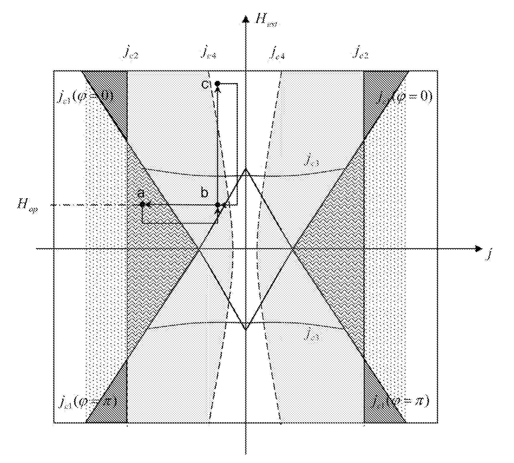
[0073]It will therefore be understood that, according to the invention, the spin-transfer torque structure can be operated as an oscillator at low current density by:[0074]setting the operating point of the spin-transfer structure in a region of bistability where the magnetization vector of the free layer can be either in a stable static state or a stable precessing state e.g. (state (a));[0075]increasing the current density in absolute values until it crosses a first threshold value (|jc1(Hop)|), thereby inducing a precession of the magnetization vector of the free layer (state (b);[0076]decreasing the current density in absolute values until it crosses back said first threshold value, the magnetizing vector of the free layer being thereby kept in said precessing state.

[0077]For switching off the oscillator, the current density is decreased in absolute values until a second threshold value is crossed (|jc4(Hop)|), i.e. the operating point is moved out of the first region of bistabi...

second embodiment

[0079]FIG. 5 illustrates a method for operating the spin-transfer structure as an oscillator, according to the invention.

[0080]This figure shows an example of operation cycle a→b→a→c→a performed at a constant current density value jop.

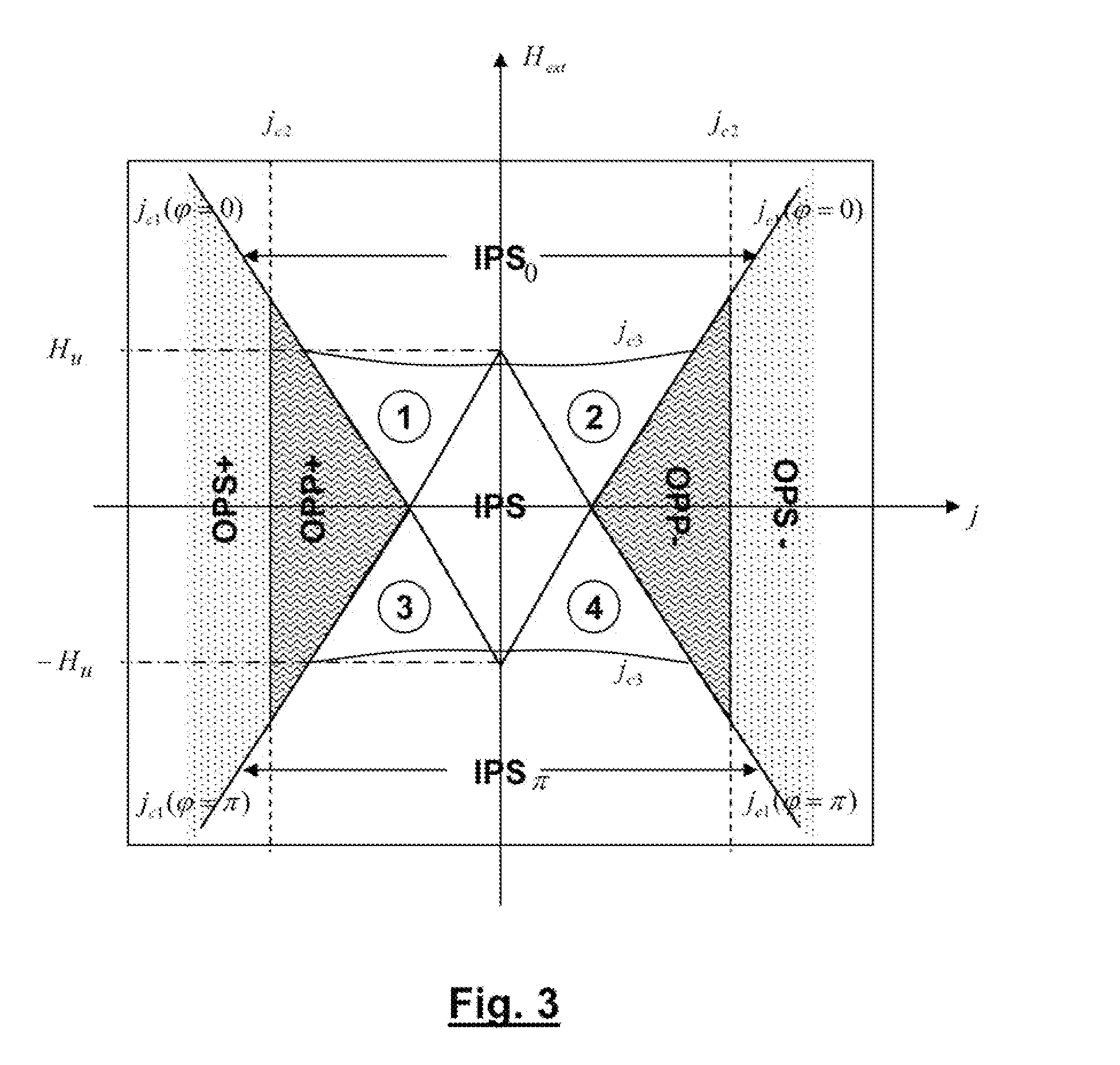
[0081]The starting state (a) is assumed static. This means, as for the first embodiment, that it lies either in the IPS region or in one of the regions (1)-(2) where the initial angle of the magnetization vector was φ=0 or in one of the regions (3)-(4) where the initial angle of the magnetization vector was φ=π. In the present instance, (a) lies in region (2) with φ=0 but the other cases may equally be considered.

[0082]The external magnetic field is decreased until it crosses a threshold value Hdown such that |jop|>|jc1(Hdown)| at which precession starts and the structure consequently generates an oscillating voltage. In the present instance, the operating point is moved to state (b) in region (4). Since the initial angle of the magnetization vector wa...

third embodiment

[0090]FIGS. 6 illustrates a method for operating the spin-transfer structure as an oscillator, according to the invention. In this embodiment, the spin torque oscillator is switched on by applying a current pulse of given polarity and switched off by applying an external magnetic field pulse of a given polarity.

[0091]More specifically FIG. 6 shows an operating cycle a→b→a→c→a in which the switching on half-cycle a→b→a is identical to a switching on half-cycle a→b→a of the first embodiment whereas the switching off half-cycle a→c→a is identical to a switching off half-cycle of the second embodiment.


PUM


Abstract

The invention relates to a method of operating a spin-transfer torque structure to generate voltage oscillations, said structure comprising a first layer of magnetic material having a fixed magnetization vector, a spacer of non magnetic material and a second layer of magnetic material having a free magnetization vector. The method includes the application of a current (jop) through said structure and a magnetic field (Hext) in the plane of the second layer. It makes use of a region of bistability and hysteretic behaviour to trigger and stop the voltage oscillations.

Description

TECHNICAL FIELD OF THE INVENTION[0001]The present invention relates to a method for generating RF oscillations, based on the principle of spin momentum transfer.BACKGROUND OF THE INVENTION[0002]Spin electronic devices are currently a topic of intensive research for various applications ranging from magnetic recording to voltage controlled oscillators (VCOs).[0003]Typically, a spin electronic device is based on a magnetic multilayer structure comprising a first ferromagnetic layer of fixed magnetization direction, also called polarization layer or pinned layer, a non-magnetic spacer of metallic or insulating material and a second ferromagnetic layer of variable magnetization orientation, also called for this reason free layer. The spacer provides for a magnetic decoupling of the first and second ferromagnetic layers. If the spacer is an insulating layer, a magnetic tunnel junction (MTJ) is obtained whereas if it is a metallic layer one obtains a so called spin valve (SV) structure. S...

Claims


Application Information

Patent Timeline
Patent Type & Authority Applications(United States)
IPC IPC(8): H03B17/00
CPCB82Y25/00H01F10/3254H01F10/329H03B15/006H01F10/3286H01F10/3268
Inventor FIRASTRAU, IOANAEBELS, URSULADIENY, BERNARD
Owner CENT NAT DE LA RECHERCHE SCI
Why Eureka
Try Eureka