
Electromagnetic relay

a technology of electromagnetic relay and relay body, which is applied in the field of electromagnetic relay, can solve the problems of relatively large dimensions of electromagnetic relay including mechanically operating parts and thus tending to become unstable, and achieve the effect of reducing thermal stress and improving the reliability of surface mounting configuration

Inactive Publication Date: 2010-02-18
FUJITSU COMPONENENT LTD
View PDF11 Cites 5 Cited by
  • Summary
  • Abstract
  • Description
  • Claims
  • Application Information

AI Technical Summary

Benefits of technology

The present invention provides an electromagnetic relay that reduces thermal stress and improves reliability in surface mounting configurations. The relay has a body with multiple terminals that project from it. One terminal has a distal end that is positioned farther away from the body than another terminal, which helps to reduce thermal stress. The second terminal can have electrical conducting properties or not. The first terminals can be arranged along the edges of the body and the second terminal can be positioned between the two sets of first terminals. Overall, this design helps to improve the reliability of the surface mounting configuration and the apparatus that includes the relay.

Problems solved by technology

During a time when the printed circuit board is passed through the heating oven in the soldering process, the electromagnetic relay including mechanically operating parts and thus having relatively large dimensions tends to become unstable.

Method used


Image

  • Electromagnetic relay
  • Electromagnetic relay
  • Electromagnetic relay

Examples


Embodiment Construction

[0021]The embodiments of the present invention are described below in detail, with reference to the accompanying drawings. In the drawings, the same or similar components are denoted by common reference numerals.

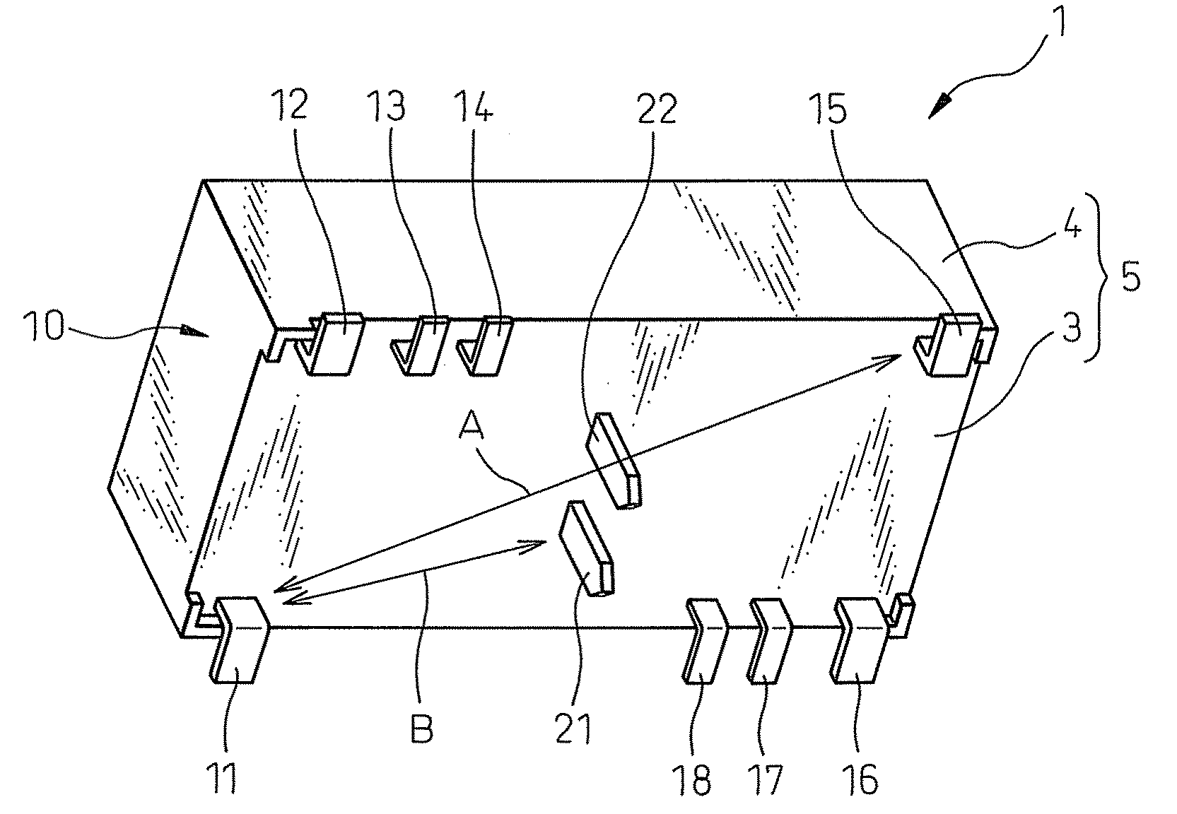
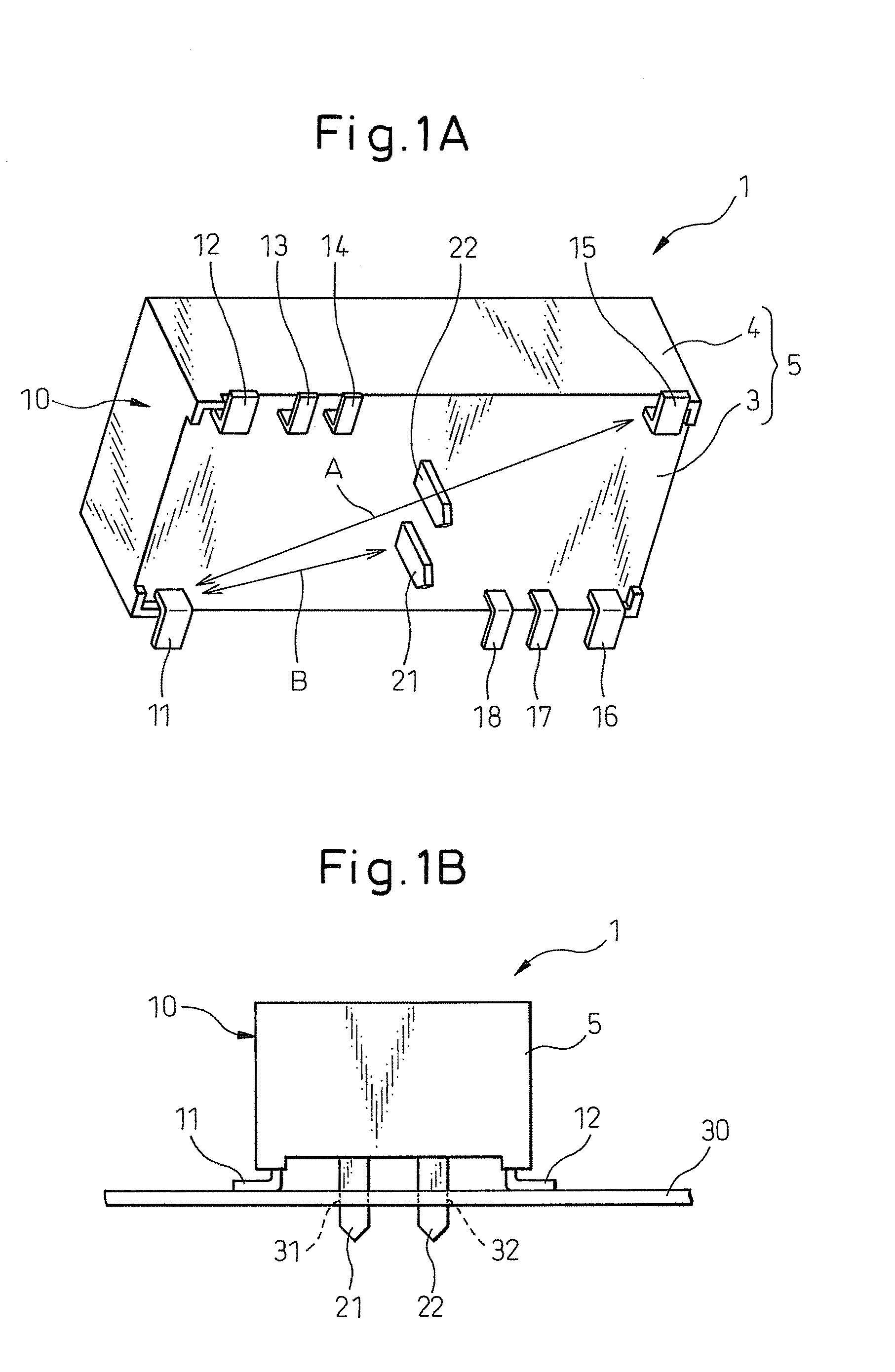
[0022]Referring to the drawings, FIG. 1A schematically shows an electromagnetic relay 1 according to an embodiment of the present invention, and FIG. 1B schematically shows the electromagnetic relay 1 mounted to a printed circuit board 30.

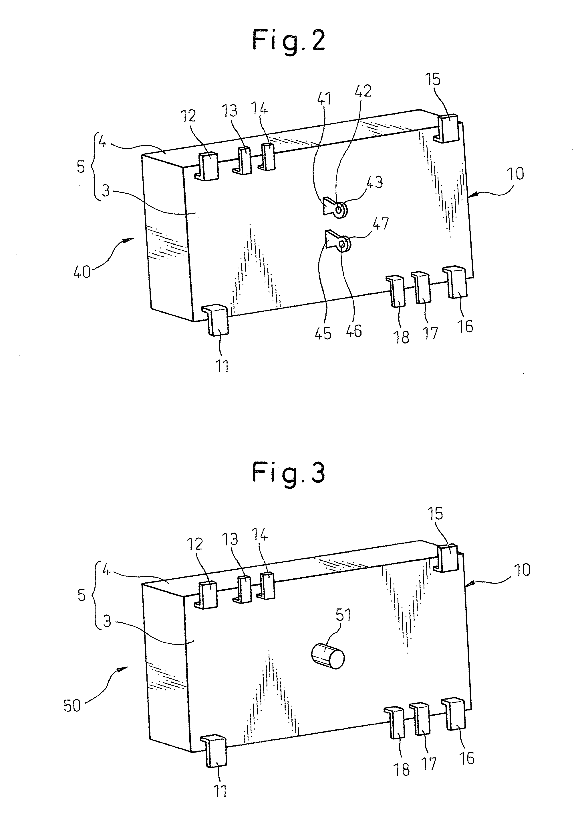
[0023]The electromagnetic relay 1 includes a body 10 constituted from a housing 5 having a rectangular parallelepiped shape and various parts (not shown), such as a coil, contained inside the housing 5. The housing 5 includes a base 3 supporting the various parts attached thereto and an upper casing 4 attached to the base 3 so as to surround the various parts. A plurality of external terminals are provided to project from the base 3 or the bottom surface of the body 10.

[0024]Some of the external terminals are bent into L-shapes and thus for...


PUM


Abstract

An electromagnetic relay including a body, a plurality of first surface-mount terminals projecting from the body, and at least one second terminal projecting from the body. Each first terminal includes a distal end portion adapted to be mounted on a surface of a circuit board. The second terminal includes a distal end portion adapted to be inserted into a through-hole of a circuit board. The distal end portion of the second terminal is positioned farther away from the body than the distal end portion of the first terminal.

Description

BACKGROUND OF THE INVENTION[0001]1. Field of the Invention[0002]The present invention relates to an electromagnetic relay having surface-mount terminals.[0003]2. Description of the Related Art[0004]In recent years, surface-mounting technology has been increasingly adopted for mounting electric / electronic components on a circuit board provided in various electric apparatuses. This is also the case for an electromagnetic relay adapted to be mounted on a circuit board.[0005]An electromagnetic relay includes various parts such as a coil, a movable contact member mechanically driven by the coil, etc., which are generally contained and supported in a housing for protection against external contaminants and thus constitute a relay body. External terminals are provided to project from the housing for mounting the electromagnetic relay on a circuit board and, in the case of a surface-mount-type electromagnetic relay, each external terminal is bent into an L-shape with the distal end portion ...

Claims


Application Information

Patent Timeline
Patent Type & Authority Applications(United States)
IPC IPC(8): H01H45/14
CPCH01H50/047H01H50/14H01H2001/5888H05K2201/10659H05K3/3421H05K3/3447H05K3/3415Y02P70/50
Inventor YOKOYAMA, KENICHIAOKI, SHIGEMITSU
Owner FUJITSU COMPONENENT LTD
Learn More