Expansion tank device, process for fabricating expansion tank device, and liquid cooling radiator

a technology of expansion tank and expansion tank, which is applied in the direction of lighting and heating apparatus, electric apparatus casings/cabinets/drawers, instruments, etc., can solve the problems of difficult to return the air to the reserve tank, insufficient radiation performance no longer available, and inability to achieve noise reduction as required, etc., to achieve efficient cooling and reduce noise

Inactive Publication Date: 2010-02-18
SHOWA DENKO KK +1
View PDF10 Cites 22 Cited by
  • Summary
  • Abstract
  • Description
  • Claims
  • Application Information

AI Technical Summary

Benefits of technology

[0046]When the expansion tank device described in par. 1) is provided with a cooling liquid circulating channel as connected to opposite-end openings of the cooling liquid channel of the tank installation base, a heat receiving unit disposed at an intermediate portion of the circulating channel, and a pump for circulating a cooling liquid through the cooling liquid channel of the installation base and the circulating channel, the cooling liquid heated by the heat receiving unit with the heat emitted by a heat generating source is cooled while being returned to the heat receiving unit by the pump via the circulating channel and the channel of the installation base. The air contained in the form of bubbles in the cooling liquid enters the bulging portion of the tank main body through the communication hole of the installation base and the through hole of the bottom plate while passing through the cooling liquid channel of the base, and is collected in the bulging portion. The air entering the bulging portion once encounters difficulty in reversely flowing into the cooling liquid channel owing to the function of the baffle plate provided around the through hole. Accordingly, the air is removed from the cooling liquid inside the circulating channel to ensure an improved cooling efficiency. Even if the cooling liquid thermally expands by being heated with the heat received from the heat generating source, the liquid flows into the bulging portion. This prevents the cooling liquid circulating channel from breaking owing to an increase in the internal pressure. Further if an excess of cooling liquid is placed in the tank main body of the expansion tank device, the impairment of cooling efficiency is avoidable even when the amount of cooling liquid decreases.
[0065]With the notebook personal computer described in par. 33), the CPU or like heat generating electronic component can be cooled efficiently, while the radiator ensures the reduction of noise.

Problems solved by technology

Accordingly, sufficient radiation performance has become no longer available by the method described above, which also fails to achieve the reduction in noise as required.
However, with the radiator disclosed in the above publication, the air in the reserve tank ingresses into the circulating tube when the display unit is closed, and it is difficult to return the air to the reserve tank when the display unit is opened, so that the radiator has the problem of being lower in cooling efficiency.

Method used


Image

  • Expansion tank device, process for fabricating expansion tank device, and liquid cooling radiator
  • Expansion tank device, process for fabricating expansion tank device, and liquid cooling radiator
  • Expansion tank device, process for fabricating expansion tank device, and liquid cooling radiator

Examples


Embodiment Construction

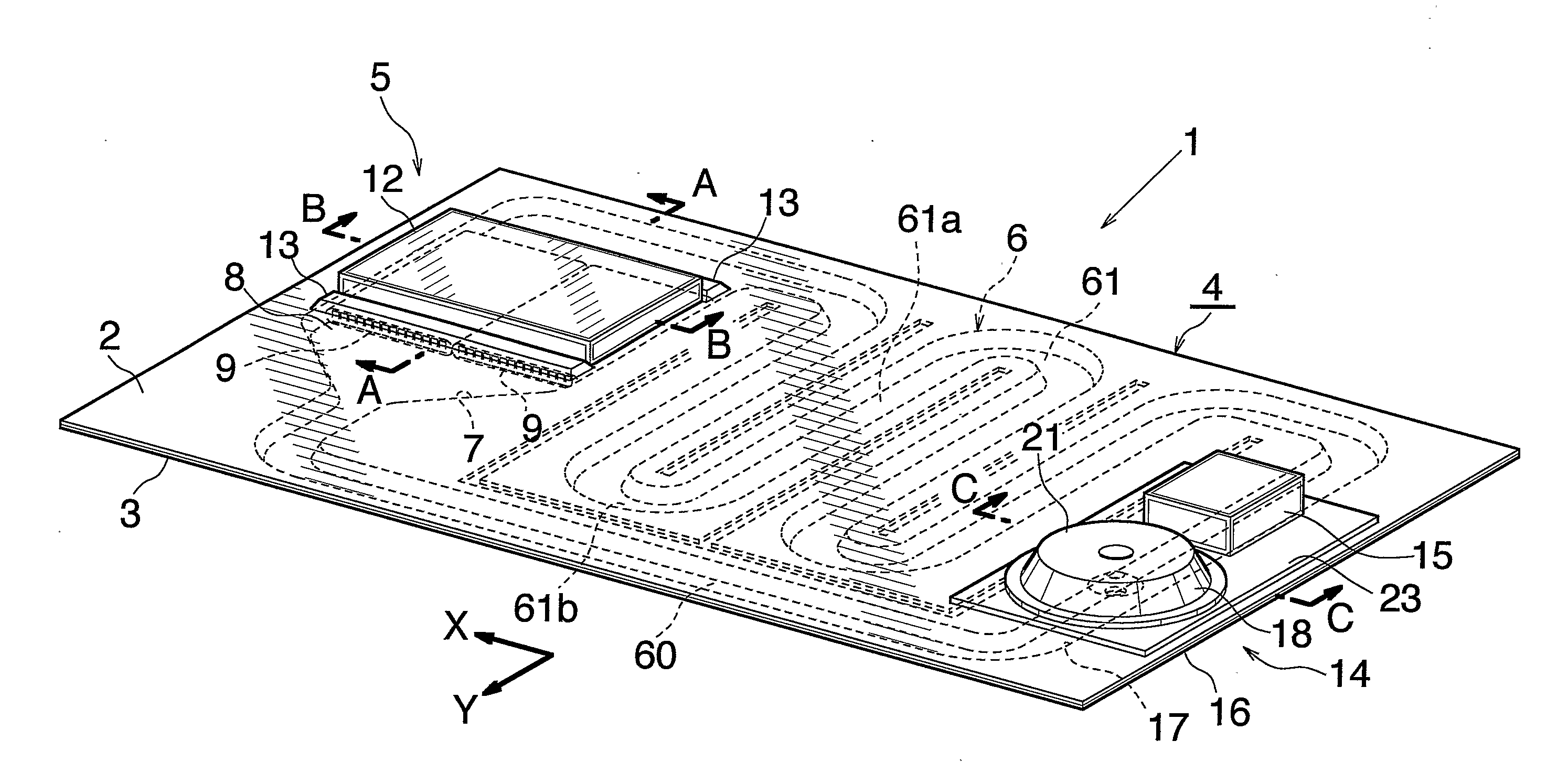
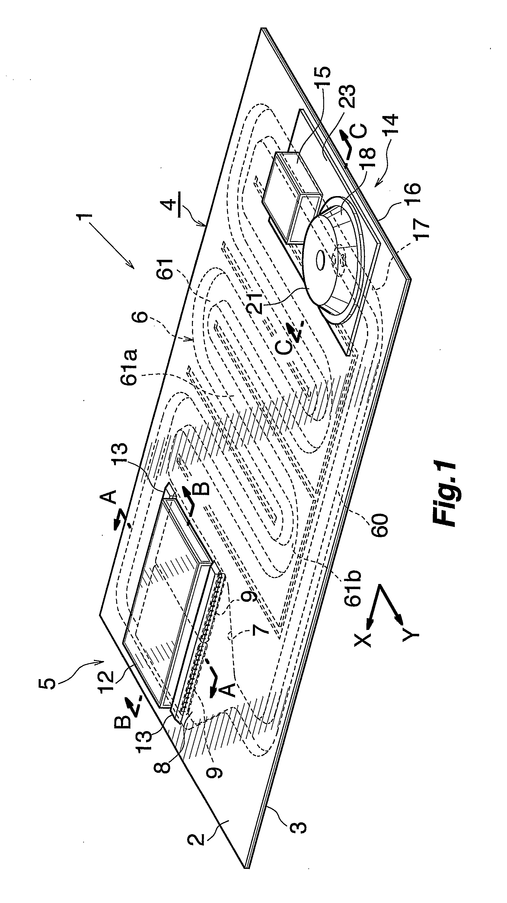
[0078]Embodiment of the present invention will be described below with reference to the drawings. In the following description, the direction indicated by the arrow X in FIG. 1 will be referred to as “left,” the opposite direction as “right, the direction indicated by the arrow Y in the same drawing as “front,” and the opposite direction as “rear.”

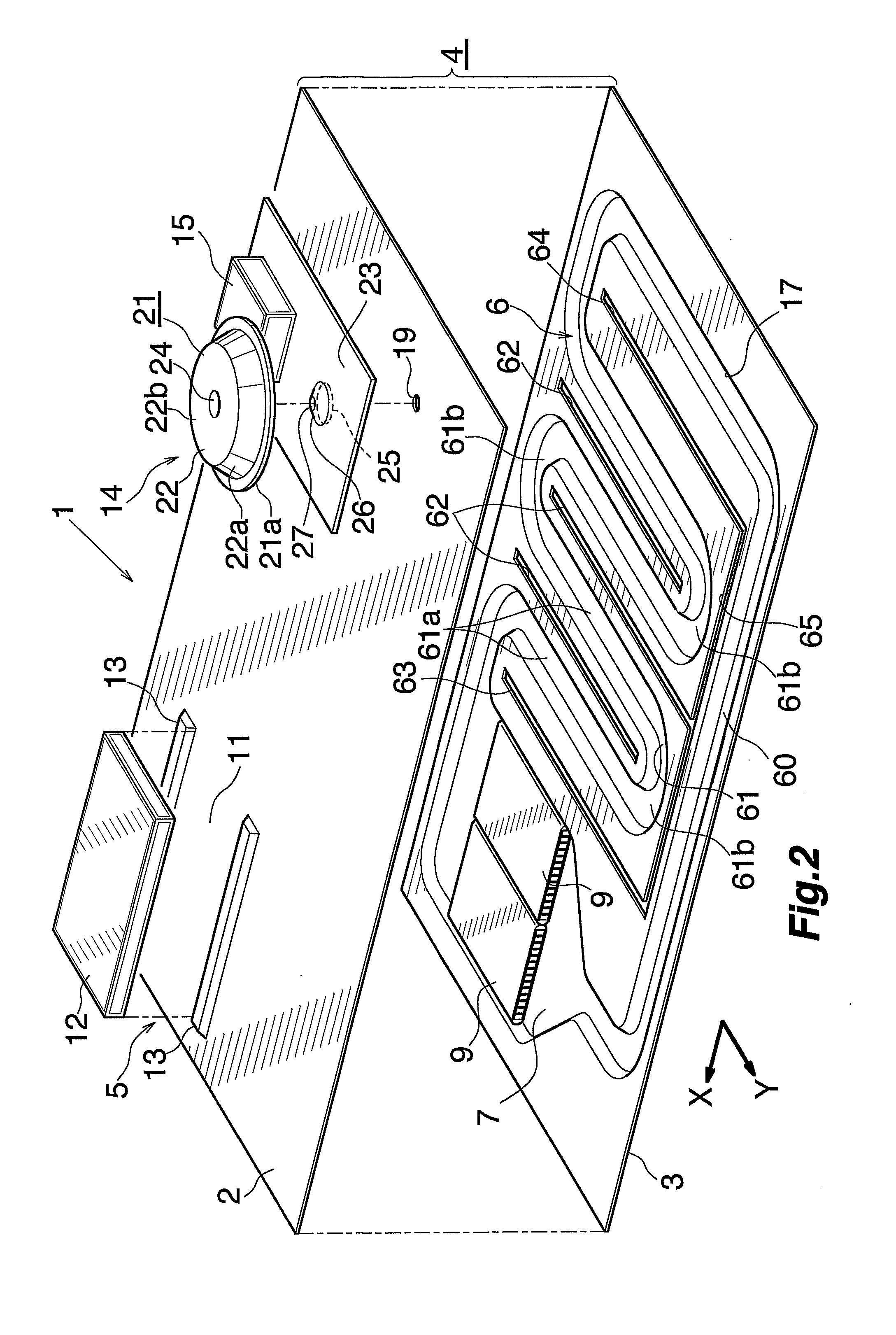
[0079]FIGS. 1 and 2 show the overall construction of a liquid cooling radiator having an expansion tank device and embodying the present invention, and FIGS. 3 to 7 show the constructions of main portions thereof. FIGS. 8 and 9 show a process for fabricating the radiator.

[0080]With reference to FIGS. 1 and 2, the liquid cooling radiator 1 has a base plate 4 in the form of a leftwardly or rightwardly elongated rectangle and composed of upper and lower two highly heat-conductive sheets, e.g., aluminum sheets 2, 3, which are joined as superposed on each other. The base plate 4 is integrally provided with a heat receiving unit 5 having a cooli...


PUM

PropertyMeasurementUnit
heightaaaaaaaaaa
heightaaaaaaaaaa
thicknessaaaaaaaaaa

Abstract

An expansion tank device 14 comprises a tank installation base 16 having a cooling liquid channel 17 and an expansion tank 18 provided on the upper surface of the installation base 16. The base 16 has a communication hole 19 for holding space above the upper surface thereof in communication with the cooling liquid channel 17. The expansion tank 18 has a tank main body 21 including an upwardly bulging portion 22 having an opening at its lower end, and a bottom plate 23 joined to the lower end of the tank main body 21 for closing the lower-end opening of the bulging portion 22 and joined to the upper surface of the tank installation base 16. The bottom plate 23 is provided at a portion thereof corresponding to the communication hole 19 with a through hole 25 communicating with the communication hole 19. The bottom plate 23 is provided with a baffle plate 26 formed along the entire circumference of the inner peripheral edge thereof defining the through hole 25 and slanting upwardly toward the center of the through hole 25. The expansion tank device 14 removes the air in the cooling liquid from the circulating system, precludes the system from breaking and prevents the decrease in the amount of cooling liquid within the circulating system.

Description

CROSS REFERENCE TO RELATED APPLICATIONS[0001]This application is an application filed under 35 U.S.C. §111(a) claiming the benefit pursuant to 35 U.S.C. §119(e) (1) of the filing date of Provisional Applications No. 60 / 520,281, No. 60 / 520,282, and No. 60 / 598,050 filed Nov. 17, 2003, Nov. 17, 2003 and Aug. 3, 2004, respectively, pursuant to 35 U.S.C. §111(b).TECHNICAL FIELD[0002]The present invention relates to expansion tank devices for use in devices for dissipating the heat generated by heat sources provided in IT devices, such as personal computers and servers, AV devices, industrial machines, tool machines, etc., a process for fabricating the expansion tank device, and liquid cooling radiators having the expansion tank device.[0003]The term “aluminum” as used herein and in the appended claims includes aluminum alloys in addition to pure aluminum. Further the term “upper” and “lower” refer respectively to the upper and lower sides of FIG. 1.BACKGROUND ART[0004]As a method widely ...

Claims


Application Information

Patent Timeline
Patent Type & Authority Applications(United States)
IPC IPC(8): G06F1/20F28D15/00F24H9/00F28F1/10F28D1/00B21D53/02F28F3/12F28F9/02H01L23/473H05K7/20
CPCF28F3/12F28F9/0231G06F1/20G06F2200/201Y10T29/4935H05K7/20272H01L2924/0002H01L23/473H01L2924/00
Inventor KATADA, YOSHINORITAGA, KAZUOISHIDA, TOMOTAKAKITAJO, SAKAE
Owner SHOWA DENKO KK
Why Eureka
Try Eureka