
Data generating device

a data generation device and data technology, applied in data switching networks, selective content distribution, instruments, etc., can solve the problems of remarkable performance decline, device itself is extremely complicated, and cannot provide an on-demand data distribution, so as to reduce the delay in processing

Active Publication Date: 2010-02-18
FUJITSU LTD
View PDF21 Cites 67 Cited by
  • Summary
  • Abstract
  • Description
  • Claims
  • Application Information

AI Technical Summary

Benefits of technology

This approach reduces processing delays and costs by allowing layer-2 switches to operate solely based on layer-2 information, efficiently forwarding multicast data to only intended recipients, thereby improving network performance and reducing unnecessary data transmission.

Problems solved by technology

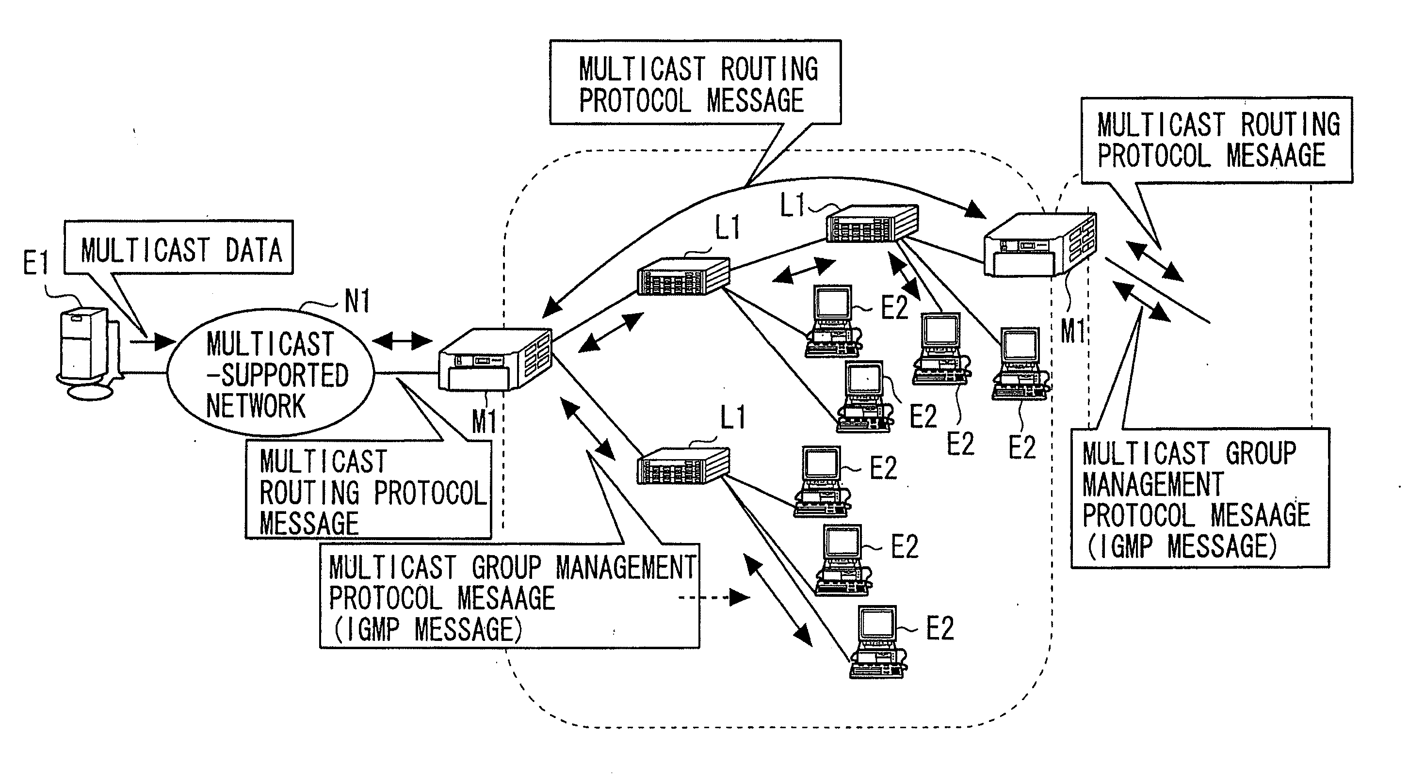
In the multicast, it is basically impossible to provide an on-demand data distribution.
The layer-2 switch for switching a frame on the basis of the layer-2 (MAC) information implements the process of referring to the layer-3 information, which causes a remarkable decline of performance of the layer-2 switch, causes the device itself to be extremely complicated and causes its cost to rise.
Namely, the multicast data are forwarded to even the client having no necessity of receiving the multicast data, and an adverse influence is exerted on other unicast communications and multicast communications.

Method used


Image

  • Data generating device
  • Data generating device
  • Data generating device

Examples


modified embodiment

[0206]The two pieces of transmitting / receiving interfaces 21 (the transmitting / receiving interfaces 21 band 21c) are provided on the side of the client, however, there may be constructed so that three or more interfaces or only one interface are to be provided without being limited to two.

[0207]Further, the multicast packet processing unit 18 is provided per transmitting / receiving interface 21, however, there may be also constructed to provide one single multicast packet processing unit 18 for managing all the transmitting / receiving interfaces.

[0208]Moreover, the data frame generating unit 27 may be constructed to read the client MAC address in whatever judging procedures.

[0209]Still further, the multicast control message judging unit 25 may be constructed to, in the case of receiving the Report message and the Query message corresponding to the IGMPv1 or the IGMPv2, convert the receipt client information management table 24A so as to support the IGMPv1 or IGMPv2. Then, the data fra...

applied examples

[0215]The forwarding device (such as the multicast router 16 implemented the forwarding device, the dedicated device 29, and the like) of the invention is applied to a contents distribution system, thereby exhibiting new effects. FIG. 27 shows an outline of a contents distribution system 38 to which the multicast router 16 is applied. The content distributions system 38 is configured by use of a server site 39 of a contents distribution network (CDN) carrier, a control center 44 of an ISP (Internet Service Provider), a network 45 of the ISP (multicast-supported network), the multicast router 16, the clients 5 and the layer-2 switch 4. The server site 39 is configured by using a user management / authentication server 40, an accounting server 41, a multicast contents distribution server 42 and a router 43. Further, the ISP network 45 includes the multicast router 16. Moreover, the layer-2 switch 4 is connected to the ISP network 45 via the multicast router 16.

[0216]In the contents dist...


PUM


Abstract

A data generating device is installed more upstream than a switching device for switching based on data of a first layer. The data generating device reads forward management information relating to a forwarding process of forward data from data of a second layer higher than the first layer, determines one or more clients corresponding to destinations of the forward data on the basis of the forward management information, and generates the same number of pieces of transmission data as the number of identified clients, and forwards each of the pieces of transmission data to the switching device in order to transmit the transmission data to each of the clients.

Description

BACKGROUND OF THE INVENTION[0001]The invention relates to a device for efficiently distributing data for multicasting in a multicast environment.[0002]The multicast has hitherto been utilized as a technology of scheming to make efficient a transmission of streaming data, etc. including multimedia data such as voices, sounds, videos, images, these combination and so on. In the multicast, it is basically impossible to provide an on-demand data distribution. The multicast has, however, a large number of merits in a distribution of the dynamic images and a distribution of the voices in realtime (Example: live relay broadcasting).[0003]In the multicast, a quantity of traffic of a certain route is kept constant at all times irrespective of the number of clients (the number of users desiring to receive data). Hence, there is a less of influence exerted on other communications. Accordingly, in the multicast, unlike unicast, there is no necessity of providing equipment such as a dedicated-to...

Claims


Application Information

Patent Timeline
Patent Type & Authority Applications(United States)
IPC IPC(8): H04L12/56H04L12/18H04L12/44H04L45/74
CPCH04L12/185H04L12/1886H04L65/4076H04N21/6405H04L29/06027H04L65/611H04L65/1101
Inventor KOBAYASHI, NAOFUMI
Owner FUJITSU LTD
Learn More