Ablation and monitoring system including a fiber optic imaging catheter and an optical coherence tomography system

a fiber optic imaging and monitoring system technology, applied in the field of ablation systems, can solve the problems of inability to provide a physician with real-time assessment, inability to generate or transmit electrical signals, and existing ablation catheters without fiber optic imaging capability

Inactive Publication Date: 2010-02-18
ST JUDE MEDICAL
View PDF13 Cites 78 Cited by
  • Summary
  • Abstract
  • Description
  • Claims
  • Application Information

AI Technical Summary

Benefits of technology

[0008]An ablation and monitoring system comprises a catheter, an optical coherence tomography (OCT) system, and an ablation generator. The catheter comprises one or more optical fibers to transmit a light beam to a tissue material and collect a reflected light from the tissue material. The OCT system is in optical communication with the catheter via the one or more optical fibers, providing the light beam to the one or more optical fibers and receiving the reflected light from the one or more optical fibers. The ablation generator is in electrical communication with the OCT system and with the catheter. The ablation generator provides radio frequency energy to the catheter for ablating the tissue material, monitors and assesses the ablation based on an information signal received from the OCT system.

Problems solved by technology

By damaging and scarring the targeted tissue, aberrant electrical signal generation or transmission may be interrupted.
Existing ablation catheters do not have fiber optic imaging capability to provide a physician with real-time assessment of the targeted tissue, tissue contact with the catheter tip, depth and volume of lesion, and other information.

Method used


Image

  • Ablation and monitoring system including a fiber optic imaging catheter and an optical coherence tomography system
  • Ablation and monitoring system including a fiber optic imaging catheter and an optical coherence tomography system
  • Ablation and monitoring system including a fiber optic imaging catheter and an optical coherence tomography system

Examples


embodiment 400

[0029]FIG. 4B shows an external view of an embodiment 400 of the distal region 240 of the catheter 110. This embodiment 400 of the distal region 240 has a plurality of openings or transparent windows 330 placed at various locations.

[0030]FIG. 4C shows a longitudinal cross sectional view of the embodiment 400 of the distal region 240 of the catheter 110 shown in FIG. 4B. For simplicity, only the optical fibers 604i terminating at openings or transparent windows 330 and the fluid lumen irrigating fluid to elution holes 320 are shown. FIG. 4C shows the hidden view (represented by broken lines) of three optical fibers placed axially and terminating at the openings or transparent windows 330 located at the distal end of the catheter 110, and two optical fibers each placed at an angle and terminating at an opening or transparent window 330 placed at a location proximal to the distal end of the catheter 110. This configuration allows the optical fibers to transmit light to and collect refl...

embodiment 600

[0043]FIG. 6 shows a diagram of an embodiment 600 of the OCT system 120, which is a five-channel OCT system using common-path interferometer.

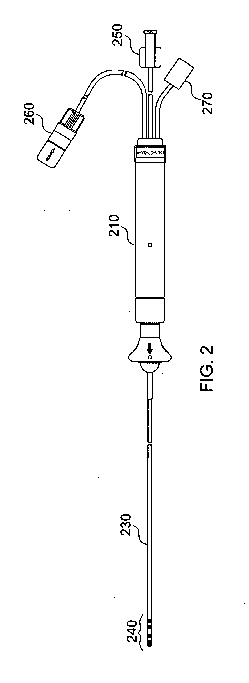
[0044]The OCT system 600 comprises an optical fiber 601, an optical switch 602, five optical fibers 604 which are connected via the fiber optic connector 270 (see FIG. 2) to five corresponding optical fibers which terminate inside the catheter 110, five optical circulators 606, five photo detectors 608, a signal combiner 610, a data acquisition card 612 which sends an analog information signal to the control module 135 of ablation generator 130. System 600 also includes a second data acquisition card 614 to send a digital control signal to the optical switch 602 to control the switch function. The data acquisition card 614 is in electrical communication with the control module 135. It is noted that this second data acquisition card 614 is not needed if the data acquisition card 612 can also output a digital control signal to the optical switch ...


PUM


Abstract

An ablation and monitoring system comprises a catheter, an optical coherence tomography (OCT) system, and an ablation generator. The catheter comprises one or more optical fibers to transmit a light beam to a tissue material and collect a reflected light from the tissue material. The OCT system is in optical communication with the catheter via the one or more optical fibers, providing the light beam to the one or more optical fibers and receiving the reflected light from the one or more optical fibers. The ablation generator is in electrical communication with the OCT system and with the catheter. The ablation generator provides radio frequency energy to the catheter for ablating the tissue material, monitors and assesses the ablation based on an information signal received from the OCT system.

Description

CROSS-REFERENCE TO RELATED APPLICATIONS[0001]This application claims the benefit of U.S. Provisional Application Ser. No. 61 / 135,872, filed on Jul. 23, 2008, entitled “Ablation and monitoring system including a fiber optic imaging catheter and an optical coherence tomography system”, which is hereby incorporated by reference in its entirety.BACKGROUND OF THE INVENTION[0002]This invention relates generally to ablation systems and catheter devices, and more specifically to ablation systems with monitoring and evaluation capabilities.[0003]Catheters are flexible, tubular devices that are widely used by physicians performing medical procedures to gain access into interior regions of the body. Certain types of catheters are commonly referred to as irrigated catheters that deliver fluid to a target site in an interior region of the body. Such irrigated catheters may deliver various types of fluid to the patient, including, for example, medications, therapeutic fluids, and even cooling flu...

Claims


Application Information

Patent Timeline
Patent Type & Authority Applications(United States)
IPC IPC(8): A61B6/02A61B18/14
CPCA61B1/015A61B5/0066A61B5/0084A61B5/6852A61B18/1206A61B18/1492A61B2218/002A61B2018/00351A61B2018/00791A61B2018/0088A61B2018/00982A61B2019/464A61B2019/465A61B2018/00029A61B2090/064A61B2090/065
Inventor NGUYEN, THO HOANGCHEN, PETER C.DE LA RAMA, ALANLIU, YU
Owner ST JUDE MEDICAL
Why Eureka
Try Eureka