Eureka AIR delivers breakthrough ideas for toughest innovation challenges, trusted by R&D personnel around the world.

Controlling ice buildup on aircraft engine and nacelle static and rotating components

Active Publication Date: 2010-02-25
RAYTHEON TECH CORP
View PDF11 Cites 36 Cited by
  • Summary
  • Abstract
  • Description
  • Claims
  • Application Information

AI Technical Summary

Benefits of technology

[0005]A turbofan engine deicing system includes a core nacelle housing a turbine. A turbofan is arranged upstream from the core nacelle. A controller manipulates the turbofan in response to detecting an icing condition for avoiding undesired ice buildup on the turbofan engine and nacelle parts. In one example, a control device is command

Problems solved by technology

During icy conditions, ice may build up on static and rotating components of the aircraft engine unless preventative measures are taken.
Ice buildup causes propulsion system operability, safety and performance difficulties.
Different techniques, such as anti-icing and deicing systems, can cause efficiency losses as well as a need for larger safety and operability margins to keep the propulsion system operational during icing conditions.
These techniques result in an increase in system weight and fuel burn.
One example anti-icing system relies upon hot compressor bleed air, which can result in up to several percent fuel burn debit during its brief usage.
Electrical heaters have also been employed, but are undesirable because they extract power from the engine.
Specialty coatings have also been used to prevent icing, but are typically costly and deteriorate over time.
Deicing systems are employed after ice formation and typically require an undesirably large amount of energy to actuate and break off ice accumulation.

Method used


Image

  • Controlling ice buildup on aircraft engine and nacelle static and rotating components
  • Controlling ice buildup on aircraft engine and nacelle static and rotating components
  • Controlling ice buildup on aircraft engine and nacelle static and rotating components

Examples


Embodiment Construction

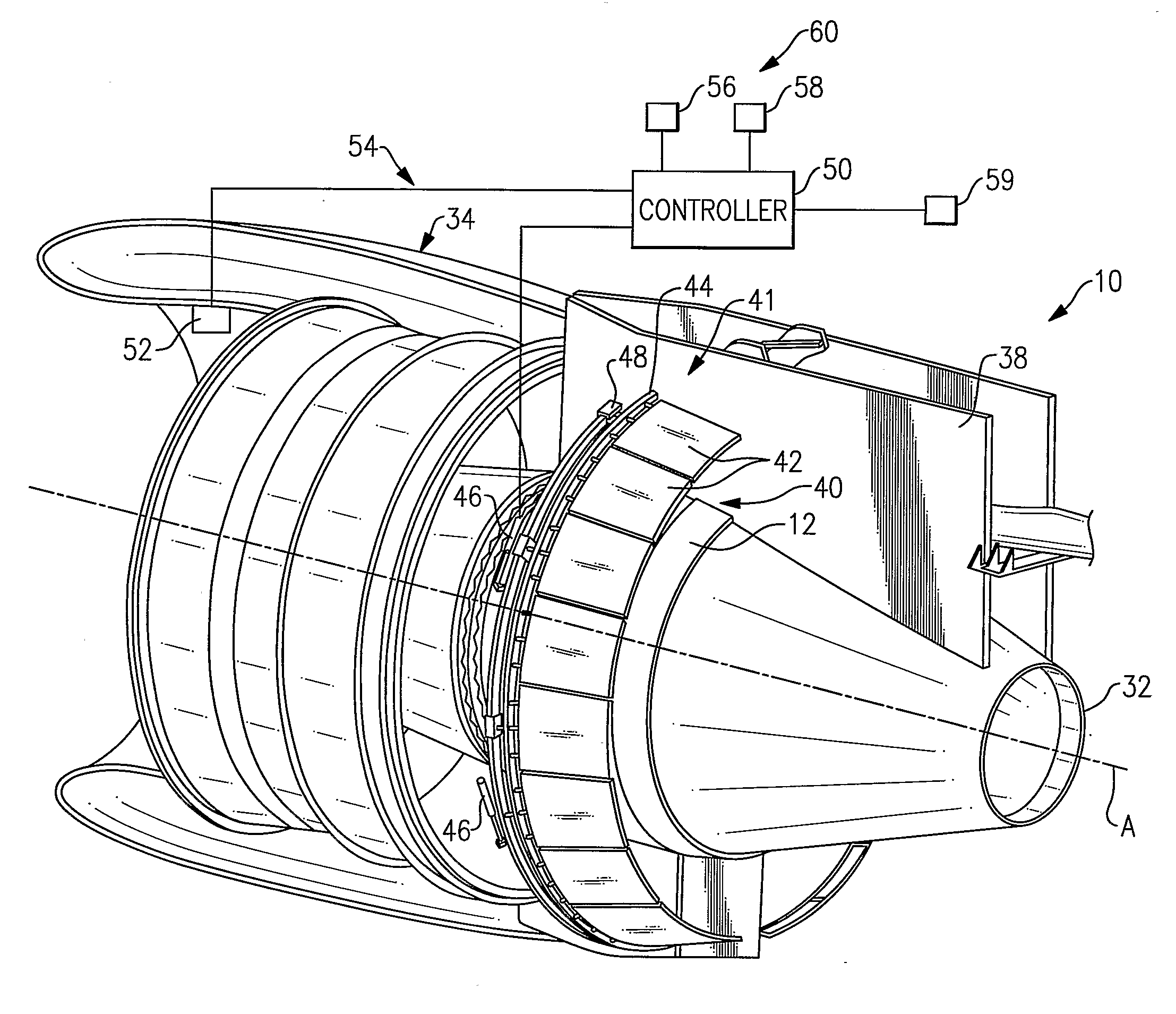
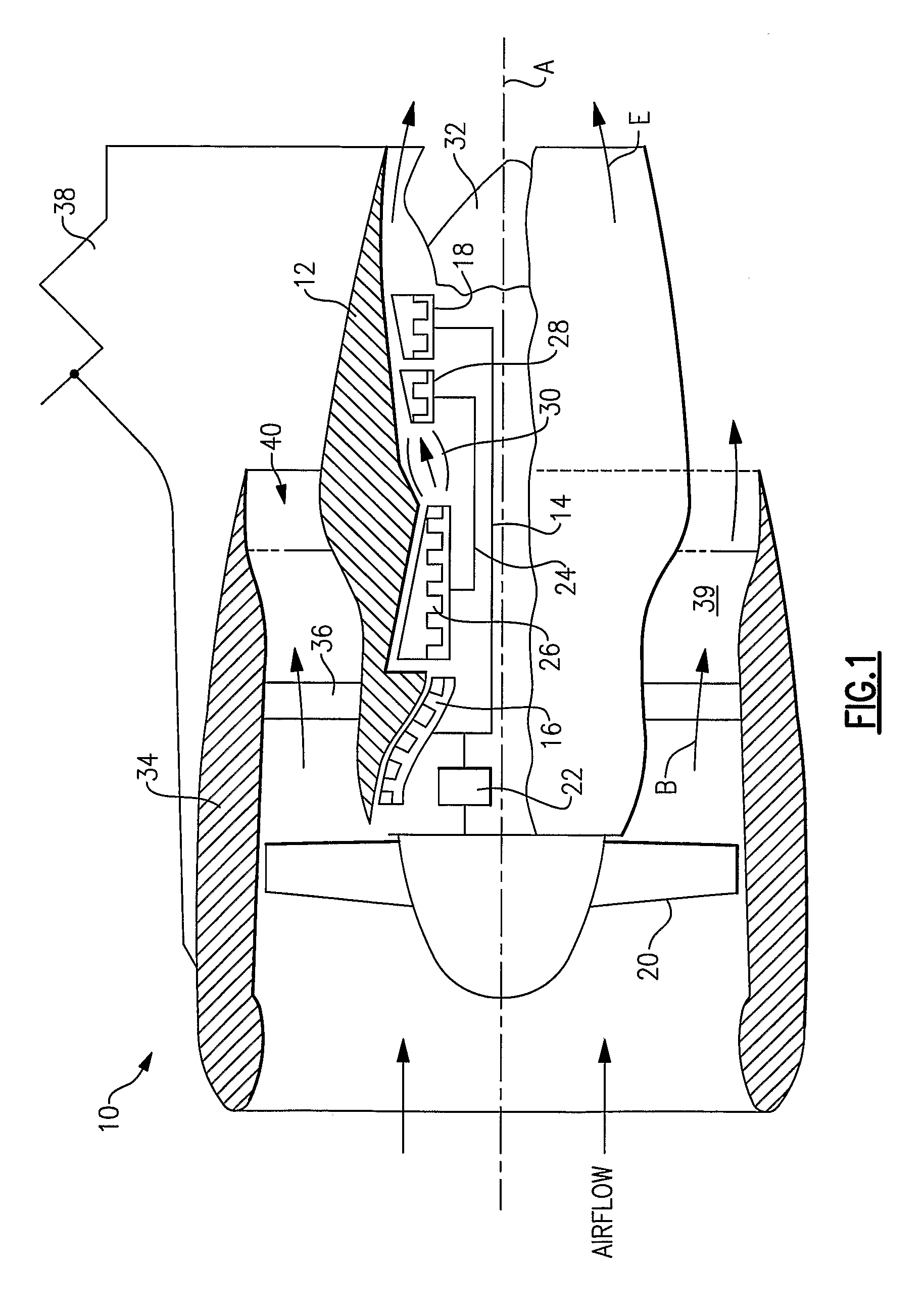
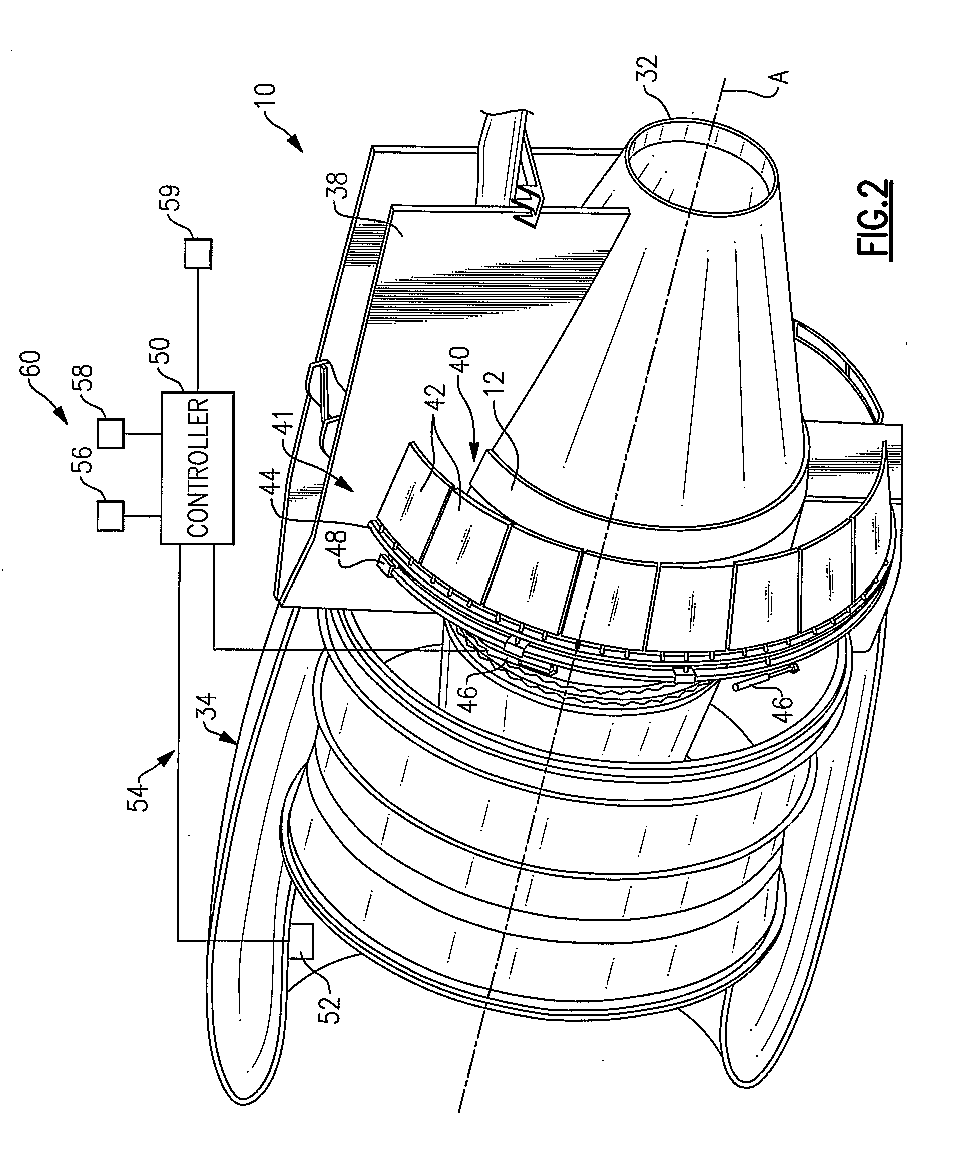
[0009]A geared turbofan engine 10 is shown in FIG. 1. A pylon 38 secures the engine 10 to an aircraft. The engine 10 includes a core nacelle 12 that houses a low spool 14 and high spool 24 rotatable about an axis A. The low spool 14 supports a low pressure compressor 16 and low pressure turbine 18. In the example, the low spool 14 drives a turbofan 20 through a gear train 22. The high spool 24 supports a high pressure compressor 26 and high pressure turbine 28. A combustor 30 is arranged between the high pressure compressor 26 and high pressure turbine 28. Compressed air from compressors 16, 26 mixes with fuel from the combustor 30 and is expanded in turbines 18, 28.

[0010]In the examples shown, the engine 10 is a high bypass turbofan arrangement. In one example, the bypass ratio is greater than 10:1, and the turbofan diameter is substantially larger than the diameter of the low pressure compressor 16. The low pressure turbine 18 has a pressure ratio that is greater than 5:1, in one ...


PUM


Abstract

A turbofan engine deicing system includes a core nacelle (12) housing a turbine. A turbofan (20) is arranged upstream from the core nacelle. A controller (50) manipulates the turbofan in response to detecting an icing condition for avoiding undesired ice buildup on the turbofan engine (10) and nacelle parts. In one example, a variable area nozzle (40) is actuated to generate pressure pulses or a surge condition to break up any ice buildup. The icing condition can be determined by at least one sensor (52) and / or predicted based upon icing conditions schedules.

Description

BACKGROUND OF THE INVENTION[0001]This invention relates to a deicing system for use with, for example, a turbofan engine.[0002]During icy conditions, ice may build up on static and rotating components of the aircraft engine unless preventative measures are taken. Ice buildup causes propulsion system operability, safety and performance difficulties. Different techniques, such as anti-icing and deicing systems, can cause efficiency losses as well as a need for larger safety and operability margins to keep the propulsion system operational during icing conditions. These techniques result in an increase in system weight and fuel burn.[0003]One example anti-icing system relies upon hot compressor bleed air, which can result in up to several percent fuel burn debit during its brief usage. Electrical heaters have also been employed, but are undesirable because they extract power from the engine. Specialty coatings have also been used to prevent icing, but are typically costly and deteriora...

Claims


Application Information

Patent Timeline
IPC IPC(8): F02K3/02F02C7/00F02C9/00
CPCB64D15/16B64D29/00F02C7/047F05D2260/80F02K1/16F05D2260/16F05D2270/44F02K1/06
Inventor JAIN, ASHOK K.WINTER, MICHAEL
Owner RAYTHEON TECH CORP
Why Eureka
Eureka Blog
Learn More