Fuel pump and a method for controlling a fuel pump

a technology of fuel pump and fuel pump, which is applied in the direction of electric control, fuel injection apparatus, charge feed system, etc., can solve the problems of reducing affecting the efficiency of the pump, and affecting the performance of the pump means, etc., to achieve good efficiency, simple manner, and good accuracy

Inactive Publication Date: 2010-02-25
SCANIA CV AB
View PDF19 Cites 14 Cited by
  • Summary
  • Abstract
  • Description
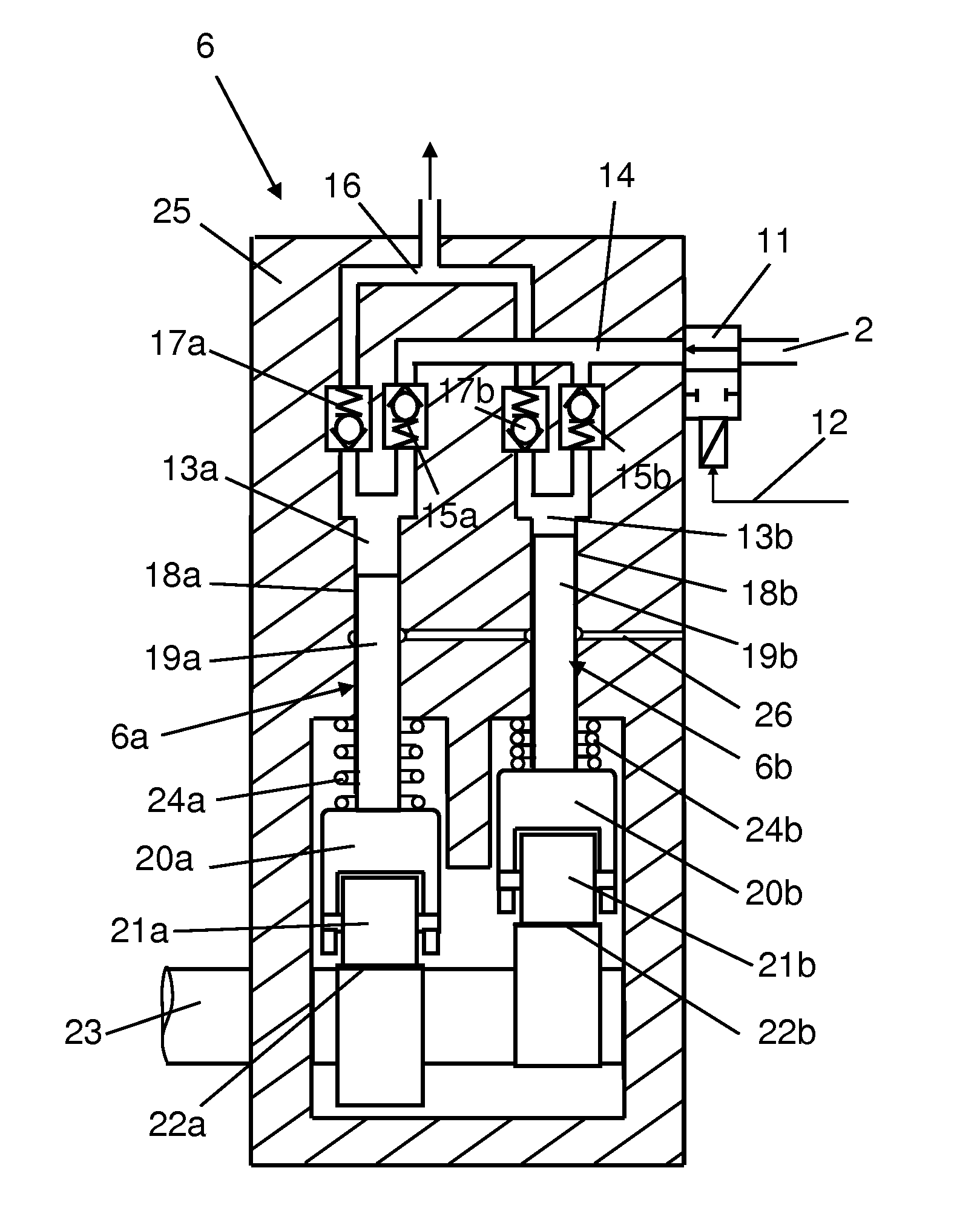
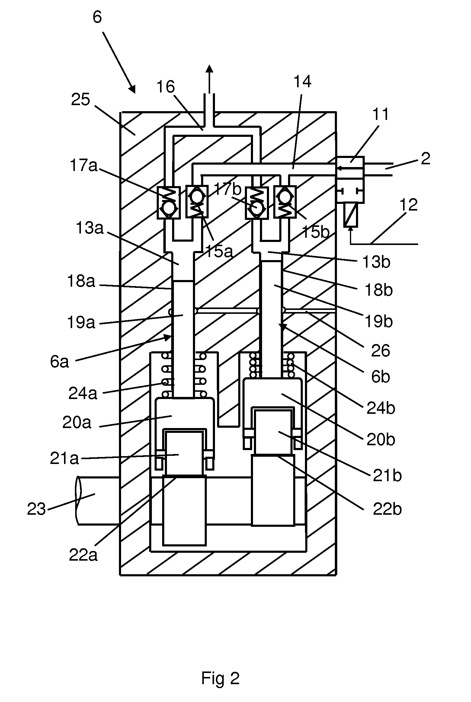
  • Claims
  • Application Information

AI Technical Summary

Benefits of technology

[0004]The object of the present invention is to provide a fuel pump and a method for controlling a fuel pump whereby fuel can with very good accuracy be delivered to the respective pump means of the fuel pump in a relatively simple manner. Other objects are that the fuel pump should have good efficiency and emit little noise substantially irrespective of the amount of fuel pressurised by the fuel pump.
[0005]The objects indicated above are achieved with the fuel pump of the kind mentioned in the introduction which is characterised by the features indicated in the characterising part of claim 1. On the basis inter alia of knowing the prevailing fuel pressure in a fuel source, the control unit can calculate how long the valve needs to be kept in the open position to allow a desired amount of fuel to be supplied to the respective pump means. Valves which are only settable in an open position and a closed position can usually be switched very quickly between said positions. Valve opening time can thus be controlled with good accuracy and hence also the amount of fuel which is supplied to the respective pump means. Such valve control thus allows individual control of the amount of fuel delivered each time to the respective pump means. The efficiency of a pump means and its noise emissions depend on the amount of fuel delivered to it. Such individual control of the amount of fuel delivered to the respective pump means allows the total amount of fuel to be distributed among the respective pump means in such a way that the fuel pump achieves overall a substantially optimum good efficiency and substantially optimum low noise emissions with the amount of fuel pressurised by the fuel pump.
[0006]According to an embodiment of the present invention, the control unit is adapted to controlling the valve so that it leads a maximum amount of fuel to one pump means and a remaining amount of fuel to the other pump means in operating situations where the fuel pump is adapted to delivering an amount of fuel which exceeds the capacity of one of the pump means. By filling at least one pump means completely with fuel and the other with a remaining amount of fuel, the fuel pump works overall at higher efficiency than if the two pump means are provided with equal distribution of fuel. Noise emissions from the fuel pump are also reduced by such distribution of the amount of fuel between the pump means as compared with equal distribution. With advantage, the control unit is adapted to controlling the valve so that it only leads fuel to one pump means in operating situations where the fuel pump is adapted to delivering an amount of fuel which corresponds to or is below the capacity of one of the pump means. One pump means is thus filled completely or partly with fuel, while no fuel is led to the other pump means. Here again the fuel pump will operate with higher efficiency and lower noise emissions than if the fuel was distributed equally between the pump means.
[0007]According to another embodiment of the present invention, the control unit is adapted to using knowledge of the performance of the respective pump means to opt to supply fuel primarily to the pump means which has the best performance. The pump means of a high-pressure pump are subject to severe stresses. The pump means are subject during operation to wear which progressively reduces their performance, but the wear of each pump means is individual, with the result that the performance of the pump means usually differs after a period of use. The service life of the fuel pump can be lengthened by using primarily the pump means which has the best performance, i.e. the least worn pump means. The control unit may accordingly be adapted to receiving information from a pressure sensor concerning the pressure imparted to the fuel by the respective pump means, and to supplying fuel primarily to the pump means which imparts the greatest pressure to the fuel. In situations where the fuel is supplied to an accumulator tank (“common rail”), the existing pressure sensor may here be used for determining the fuel pressure in the accumulator tank at the times when the respective pump means deliver pressurised fuel to the accumulator tank.
[0008]According to another embodiment of the present invention, the pump means are of substantially identical configuration and are run at a mutual phase displacement that enables them to pressurise fuel in their respective spaces during different periods of time. Using substantially identical pump means makes it possible for the fuel pump to pressurise fuel to a corresponding pressure and in a corresponding quantity irrespective of which pump means is used. Pump means pressurising fuel during different periods of time makes it possible for fuel from one pump means at a time to be led to, for example, an accumulator tank. With advantage, the pump means are operated at a mutual phase displacement of 180° C. in a work cycle of 360°. Thus one pump means pressurises fuel while at the same time the other pump means receives fuel. The fuel pump may of course comprise more than two pump means run at suitable phase displacements.
[0009]According to another embodiment of the present invention, said pressure-generating means is a piston. A piston which has a relatively small contact surface with the fuel in the respective spaces of the pump means can with advantage be used for creating very high fuel pressure in the spaces. Said fuel source preferably contains fuel at a substantially constant pressure, making it relatively easy for the control unit to calculate the time for which the valve needs to be placed in the open position to allow a desired amount of fuel to be supplied to a pump means. The valve may be a solenoid valve. Solenoid valves have the characteristic of being switchable very quickly between a closed position and an open position. It is nevertheless also possible to use other types of valves which are only settable in a closed position and an open position.

Problems solved by technology

The pump means of a high-pressure pump are subject to severe stresses.
The pump means are subject during operation to wear which progressively reduces their performance, but the wear of each pump means is individual, with the result that the performance of the pump means usually differs after a period of use.

Method used


Image

  • Fuel pump and a method for controlling a fuel pump
  • Fuel pump and a method for controlling a fuel pump
  • Fuel pump and a method for controlling a fuel pump

Examples


Embodiment Construction

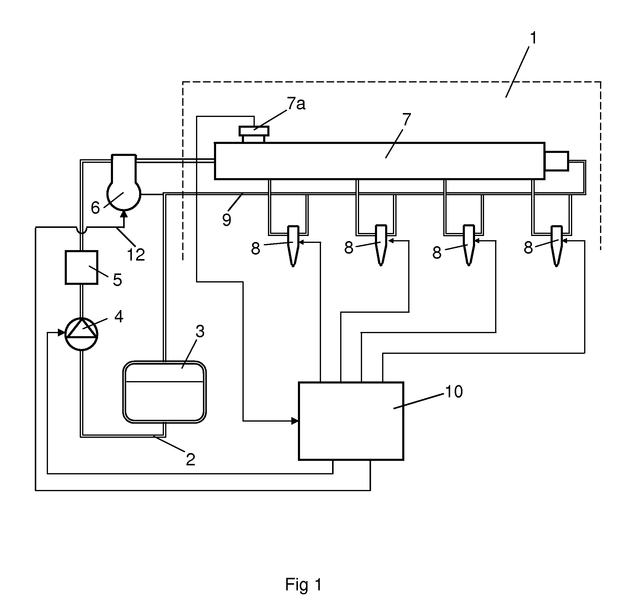
[0013]FIG. 1 depicts an injection system for injecting fuel at a very high pressure in a combustion engine here exemplified as a diesel engine 1. Injecting the fuel at a very high pressure may reduce discharges of emissions from the diesel engine 1. The injection system and the diesel engine 1 may be fitted in a heavy vehicle. The injection system comprises a fuel line 2 for supplying fuel from a fuel tank 3 to the respective cylinders of the diesel engine 1. A first fuel pump 4 is arranged in the fuel line 2 to transfer fuel from the fuel tank 3 to a second fuel pump in the form of a high-pressure pump 6 via a filter 5. The high-pressure pump 6 is adapted to pressurising the fuel so that it is fed at a high pressure into an accumulator tank 7 which takes the form of a so-called “common rail”. Injection means 8 are arranged at each of the connections between the accumulator tank 7 and the respective cylinders of the diesel engine 1. A return line 9 is adapted to leading fuel not bur...


PUM


Abstract

A fuel pump and a method for controlling a fuel pump. At least two pumps run at a mutual phase displacement such that they are able to receive fuel during different periods of time. A control unit causes a valve, which is only settable in an open position and a closed position, to lead a desired amount of fuel to the respective pump. The control unit places the valve in the open position for a variable portion of the periods so that an individually controlled amount of fuel is led to the respective pump during those periods. Maintenance of good efficiency of the fuel pump and low noise emissions is thus made possible in operating situations where the fuel pump delivers a reduced amount of fuel.

Description

BACKGROUND TO THE INVENTION, AND STATE OF THE ART[0001]The present invention relates to a fuel pump and a method for controlling a fuel pump according to the preambles of claims 1 and 11.[0002]One way of reducing discharges of emissions from diesel engines is to inject the fuel at a very high pressure. A so-called “common rail” system is commonly used for effecting injection at a high pressure in the combustion spaces of a diesel engine. A common rail system comprises a high-pressure pump which pumps fuel at a high pressure to an accumulator tank (“common rail”). The fuel in the accumulator tank is intended to be distributed to all the cylinders of the combustion engine. Fuel from the accumulator tank is injected into the combustion spaces of the respective cylinders by electronically controlled injection means.[0003]Conventional high-pressure pumps which deliver fuel to an accumulator tank usually comprise at least two pump means. The pump means work alternately so that when one pu...

Claims


Application Information

Patent Timeline
Patent Type & Authority Applications(United States)
IPC IPC(8): F02M37/04F02M37/00
CPCF02D41/3845F02M59/08F02M63/023F02M59/366F02M59/102F02M63/0225
Inventor KYLSTROM, KIMFLINK, TOMAS
Owner SCANIA CV AB
Why Eureka
Try Eureka