

System and method for separation and handling of construction, demolition and garbage materials
- Summary
- Abstract
- Description
- Claims
- Application Information
AI Technical Summary
Problems solved by technology
Method used
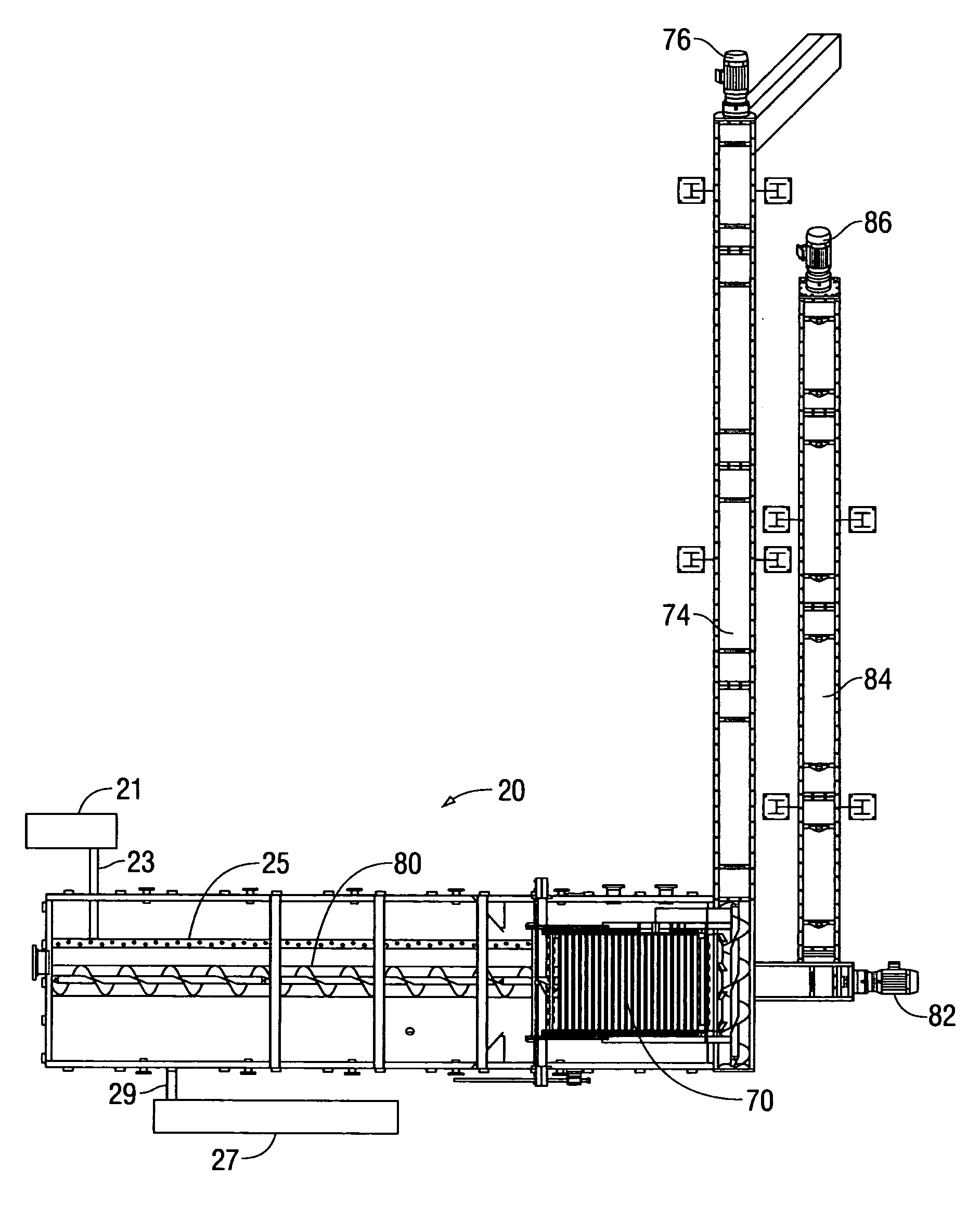
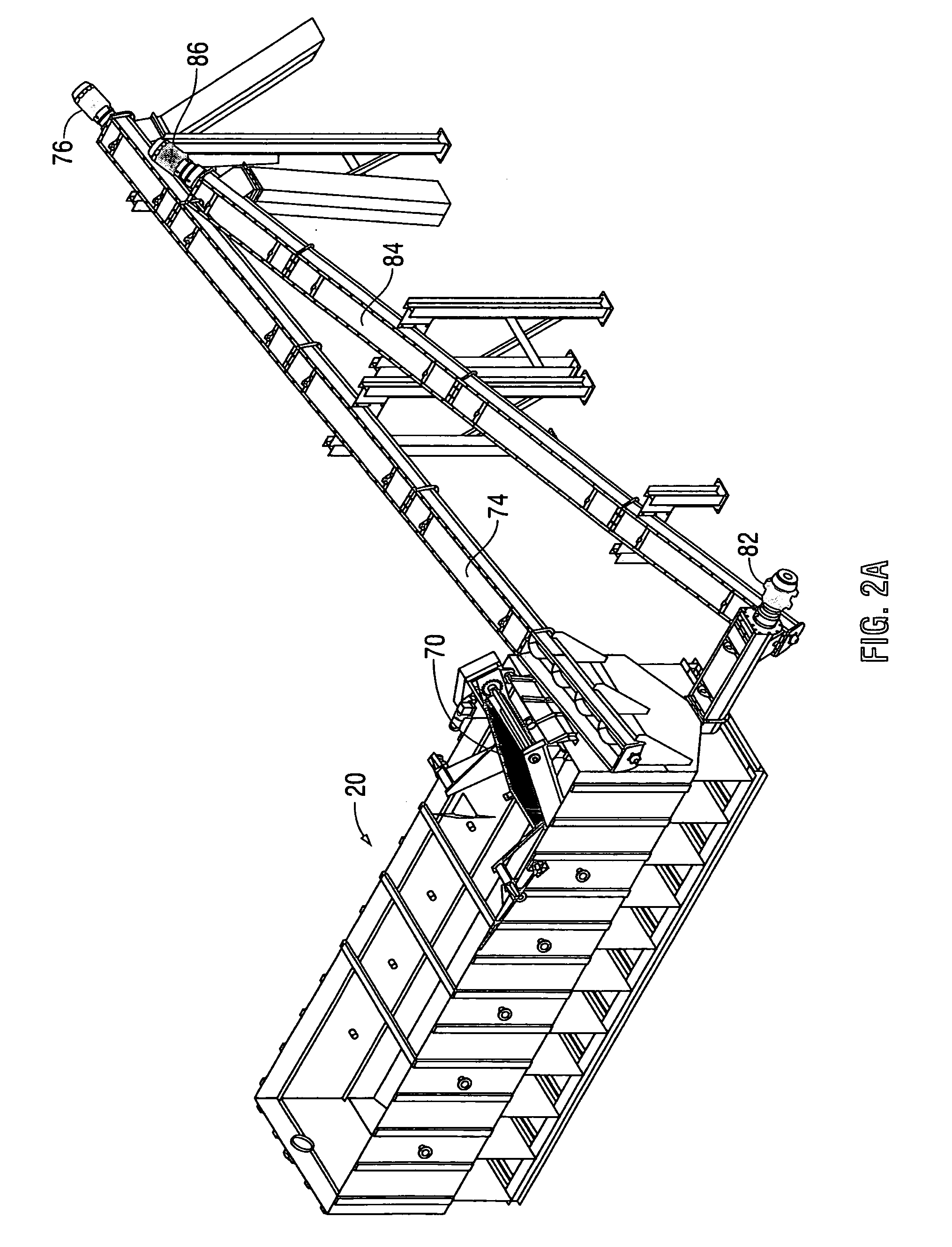
Image

Examples
Embodiment Construction
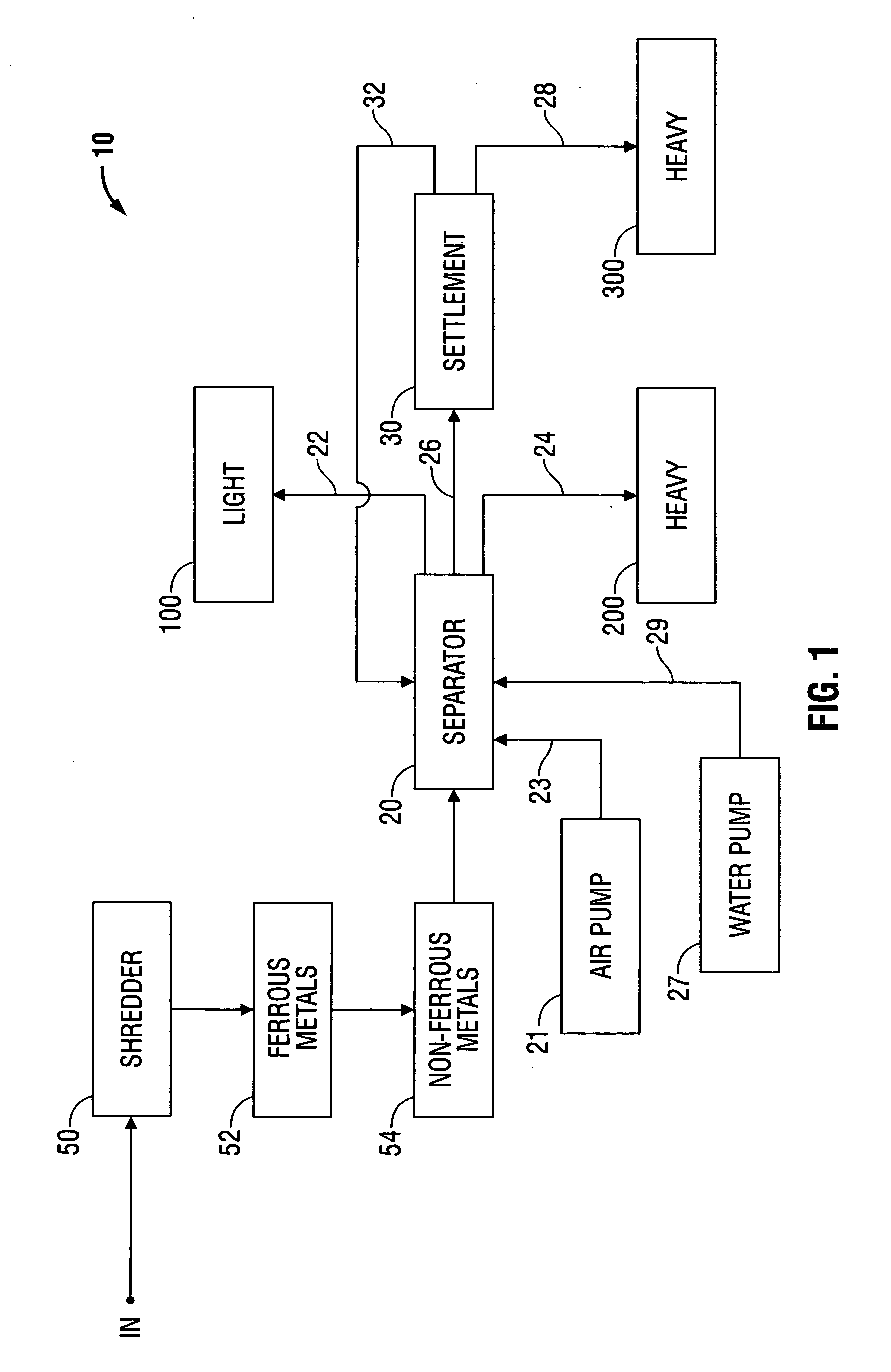
[0017]Referring now to FIG. 1, there is illustrated, in block diagram, the system 10 according to the invention in which the refuse / waste material, whether it be C&D materials, or garbage, or the like, is dumped from the “in” input location into the shredder 50. The shredder 50 is preferably of the conventional variable size type, sometimes referred to as a “(+) or (−)” type, for example a 3″, + or −1″. Depending upon the intended final use of the output product of the system 10, the shredder 50 can produce larger or smaller shreds.
[0018]The output of the shredder 50 is fed into a conventional ferrous metal detector 52 which uses the magnetic attraction of the ferrous materials to pick out and remove such ferrous materials from the mix.
[0019]The mix is also fed through a conventional non-ferrous metal detector 54, which uses eddy currents to pick out and remove such non-ferrous materials, for example, aluminum cans, from the mix. It is of no consequence whether the ferrous metal mat...
PUM
 Abstract
Description
Claims
Application Information