

Frequency locking structure applied to phase-locked loops
a phase-locked loop and locking structure technology, applied in the direction of pulse automatic control, resonance circuit tuning, electrical apparatus, etc., can solve the problems of deteriorating stability of the clock, and achieve the effect of reducing the clock jitter of the oscillator output signal and improving the jitter of the reference input signal
- Summary
- Abstract
- Description
- Claims
- Application Information
AI Technical Summary
Benefits of technology
Problems solved by technology
Method used
Image

Examples
Embodiment Construction
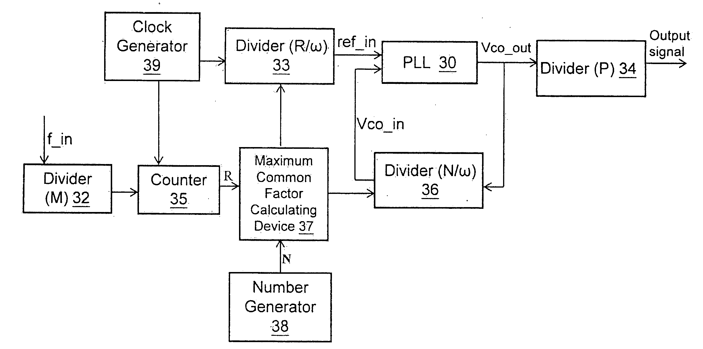
[0016]The invention is directed to a frequency locking structure applied to phase-locked loops. The difference between a reference input signal (ref_in) and an oscillator output signal (Vco_out) is reduced by utilizing a common factor to prevent the oscillator output signal (Vco_out) from clock jitter.
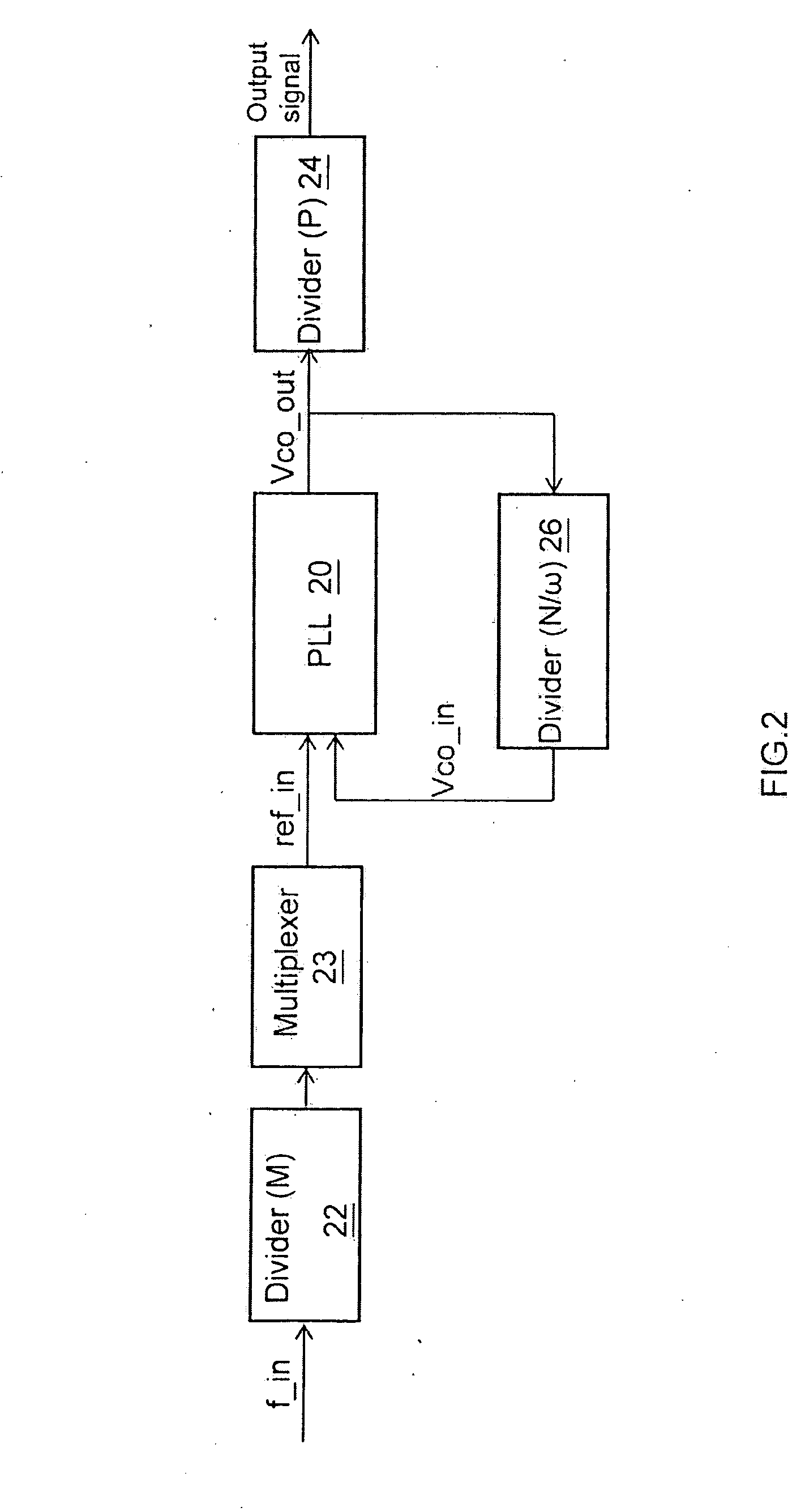
[0017]FIG. 2 is a schematic block diagram illustrating an example frequency locking structure in accordance with one embodiment of the invention. A first divider 22 receives an input signal (f_in) and divides the input signal (f_in) by a first constant factor (M). A multiplexer 23 couples the first divider 22 to receive a signal from the first divider 22 and multiplies the signal from the first divider 22 together with a common factor (ω) to output a reference input signal (ref_in). A phase-locked loop 20 couples the multiplexer 23, receives the reference input signal (ref_in) and a feedback signal (Vco_in) to output an oscillator output signal (Vco_out). A second divider 26 couples th...
PUM
 Abstract
Description
Claims
Application Information