LED cooling system

a cooling system and led technology, applied in the field of led lights, can solve the problems of reducing the efficiency of the light generated projection, unsatisfactory for providing a high intensity focused or unfocused light beam, and being much more difficult to implement, so as to achieve the effect of operation efficiency

Inactive Publication Date: 2010-02-25
HAWKEYE DISTRIBUTING
View PDF17 Cites 49 Cited by
  • Summary
  • Abstract
  • Description
  • Claims
  • Application Information

AI Technical Summary

Benefits of technology

[0006]In accordance with the present invention there is provided a high intensity LED light source which because of its intensity creates heat during operation of the LED. Therefore, it is an object of the invention to provide use of a liquid source to provide cooling to the LED by mounting the LED directly to a heat sink metallic layer, and passing the liquid immediately adjacent to the heat sink layer with a sufficient flow rate so as to cool the LED to an optimum operating temperature and hence operational efficiency.

Problems solved by technology

Such rear reflector use greatly diminishes the efficiency of the projection of the light generated by the LED, and thus is unsatisfactory for providing a high intensity focused or unfocused light beam of the apparatus of the invention.
This design utilizes two liquid heat source absorbers and is very complex, and further is much more difficult to implement that the cooling system taught by the present invention.

Method used


Image

  • LED cooling system
  • LED cooling system
  • LED cooling system

Examples


Embodiment Construction

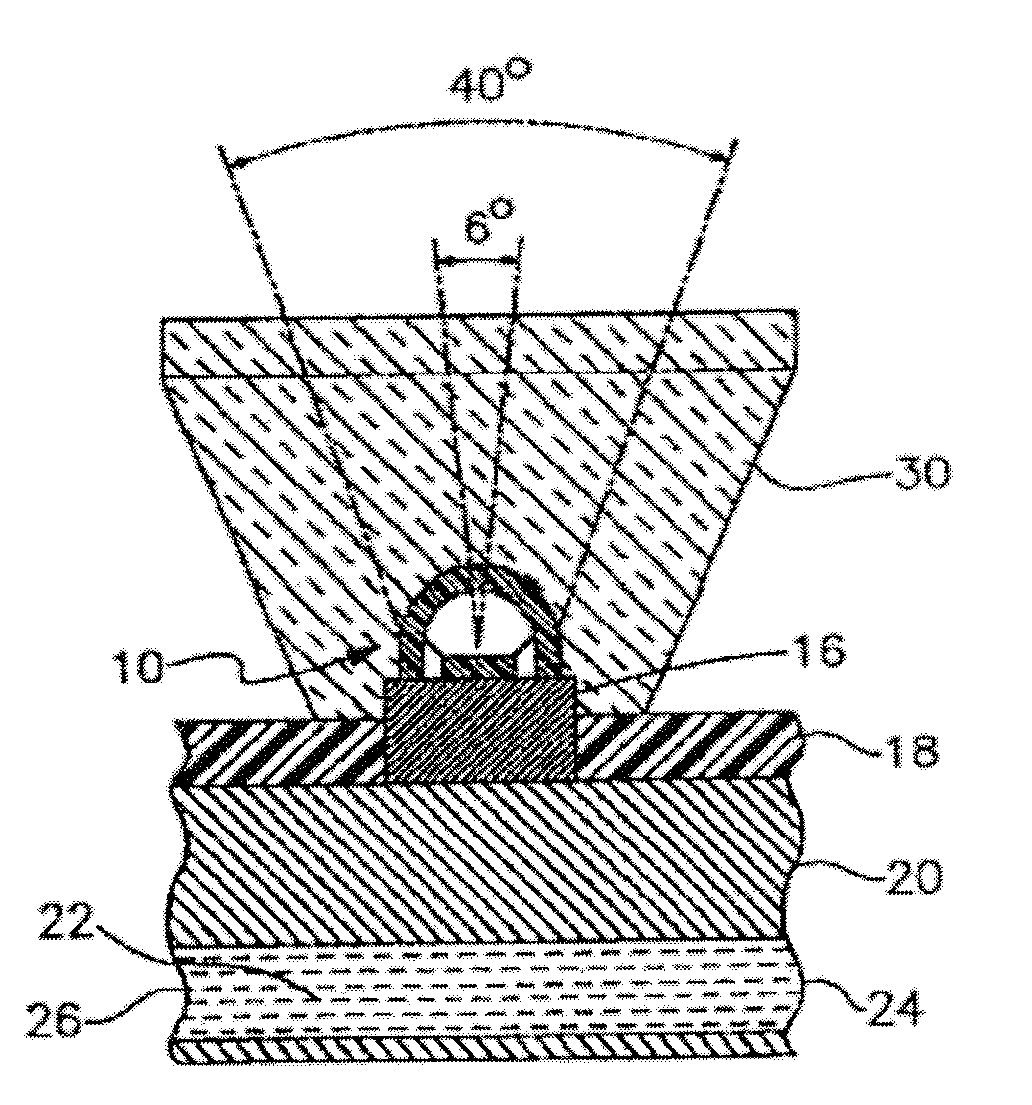
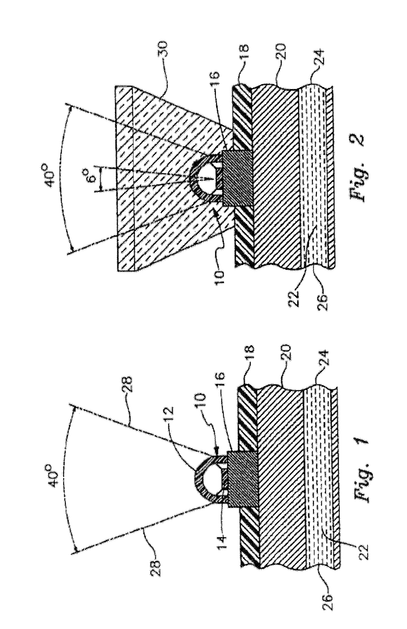
[0015]The present invention provides a high intensity LED light which can operate at its best high intensity efficiency because of the combination of a very simplified cooling system to remove heat generated by the operation of the LED, and thus promote longevity of the LED, along with optimum performance thereof.

[0016]Referring first to FIG. 1 of the drawings, 10 indicates generally a LED, which is a high intensity light source that usually operates with an electric draw of at least about 1 amp, and puts out a light intensity of between 700 and 1200 lumens. It is this type of LED that generates heat which can affect the operating characteristics, life, etc. The LED 10 is typically with a polymer outer cover 12, the actual structure of the LED at 14, and a metallic mount 16, which is secured to a printed circuit board 18. The board 18 is directly in contact with a heat sink layer 20, meaning that the bottom surface of the mount 16 is in direct and intimate contact with the heat sink...


PUM


Abstract

The invention relates to a LED cooling system that effects cooling of the LED's during use, and helps the LED's have a longer operating function, and uses less electricity for the LED's to operate. The use of cooling also provides a steadier light and has greater efficiency.

Description

FIELD OF INVENTION[0001]The present invention pertains to LED lights which generate substantial heat during operation, and more particularly the provision of a method to cool the LED during operation to facilitate longer life to the LED, assure a steady light output during operation, and operation at the least power usage rate.[0002]Some prior art apparatus have used relatively high-powered LED's to generate a desired high light output to be sufficient for the lighting requirement. Such LED's typically generate so much heat that a heat sink is required. Heretofore, the prior art has not been able to satisfy the requirement of an adequate heat sink or cooling system for a high intensity LED light generation.DISCUSSION OF THE RELATED ART[0003]Several attempts to solve the problems described hereinabove have been made in the prior art. For example, published U.S. Pat. No. 6,955,444 published Jun. 2, 2005, and issues as a patent on Oct. 18, 2005 for Surgical Headlight by Sushil Gupta, t...

Claims


Application Information

Patent Timeline
Patent Type & Authority Applications(United States)
IPC IPC(8): F21V29/00
CPCF21V29/30F21Y2101/02H05K1/0204H05K2201/10416H05K3/0061H05K2201/064H05K2201/10106H05K1/0272F21Y2115/10F21V29/70F21V29/56
Inventor MEDINIS, DAVID M.
Owner HAWKEYE DISTRIBUTING
Why Eureka
Try Eureka