Method of Wavelength Alignment for a Wavelength Division Multiplexed Passive Optical Network

a wavelength division multiplexed passive optical network and wavelength alignment technology, applied in the field of optical communication networks, can solve the problems of colorless optical transmitters, wdm pon critical component device costs slowed their integration into telecommunications networks, and the cost of wavelength-specific optical transmitters presented an obstacle to widespread implementation of wdm pon

Active Publication Date: 2010-02-25
LG ERICSSON
View PDF5 Cites 29 Cited by
  • Summary
  • Abstract
  • Description
  • Claims
  • Application Information

AI Technical Summary

Benefits of technology

[0009]In another aspect, the invention features a WDM system that includes a broadband light source, a demultiplexer, a laser and a control module. The broadband light source generates broadband light having a dithered optical power and a wavelength spectrum that includes a plurality of WDM wavelengths. The demultiplexer is in optical communication with the broadband light source and generates a spectrally-sliced optical signal having a wavelength spectrum that includes a WDM wavelength. The laser is in communication with the demultiplexer to receive the spectrally-sliced optical signal. The laser generates a WDM signal having a wavelength in the wavelength spectrum of the spectrally-sliced optical signal. The control module is in communication with the laser and determines a dithered optical power of the laser. The control module generates a control signal to adjust a parameter of the laser to thereby align the wavelength of the WDM signal to the wavelength spectrum of the spectrally-sliced optical signal.
[0010]In yet another aspect,

Problems solved by technology

Initially, the device costs for critical components of WDM PONs slowed their integration into telecommunications networks.
In particular, the cost of wavelength-specific optical transmitters presented an obstacle to widespread implementation of WDM PONs.
The ef

Method used


Image

  • Method of Wavelength Alignment for a Wavelength Division Multiplexed Passive Optical Network
  • Method of Wavelength Alignment for a Wavelength Division Multiplexed Passive Optical Network
  • Method of Wavelength Alignment for a Wavelength Division Multiplexed Passive Optical Network

Examples


Embodiment Construction

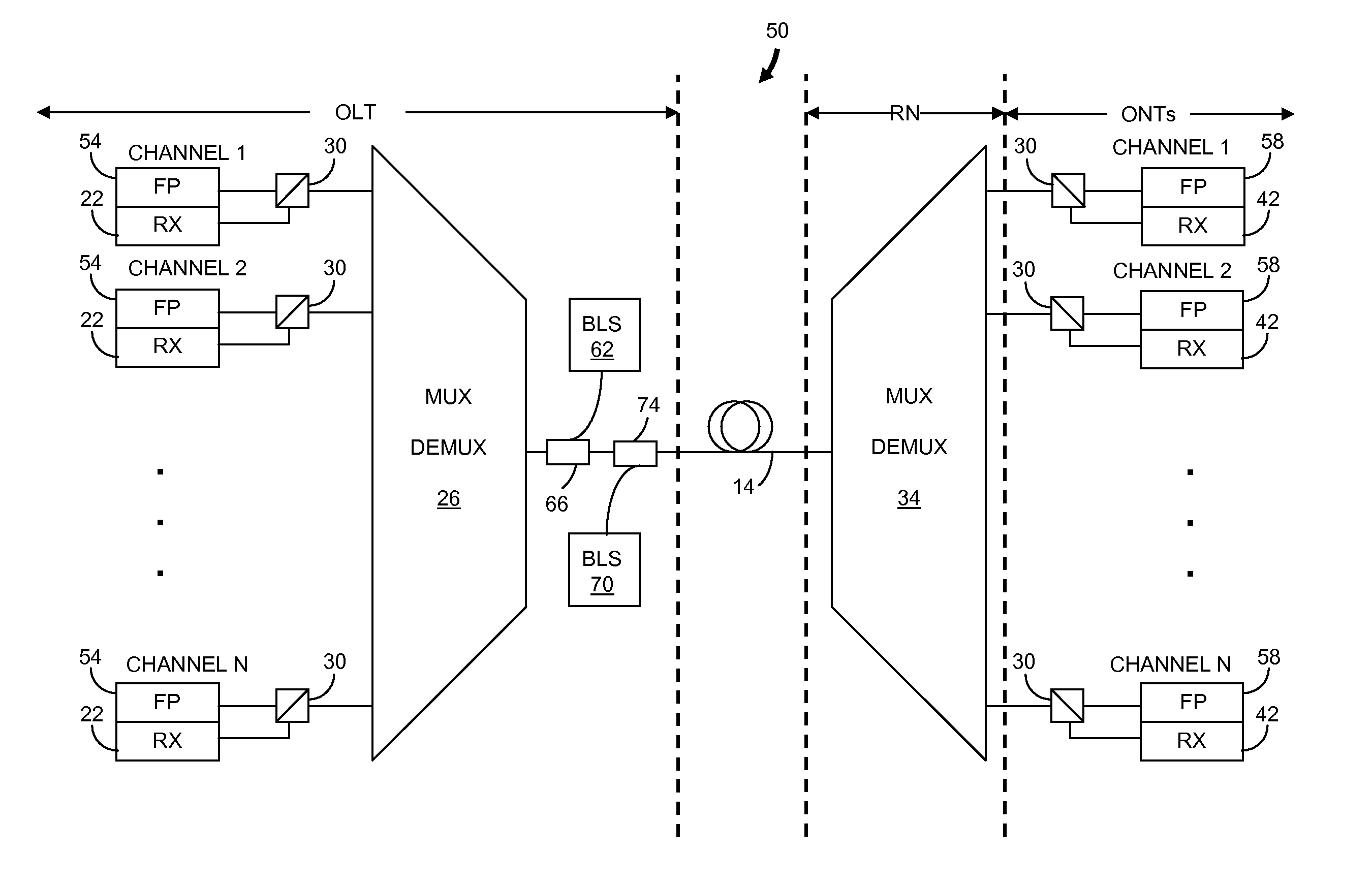
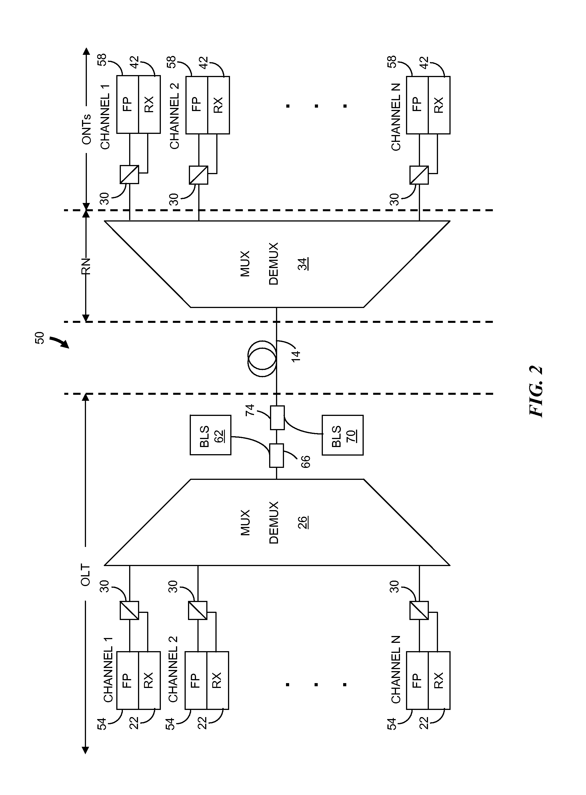
[0025]In brief overview, the invention relates to a method for controlling the wavelength of a laser in a WDM system. The method includes generating broadband light having a dithered optical power and a wavelength spectrum that includes multiple WDM wavelengths. The broadband light is spectrally filtered to generate a spectrally-sliced optical signal having a wavelength spectrum that includes one of the WDM wavelengths. The spectrally-sliced optical signal is injected into a laser, such as a Fabry-Perot laser, and a dithered optical power of the laser is determined. The method provides for control of a parameter of the laser in response to the detected dithered optical power. Control of the parameter enables alignment of a wavelength of the laser to the wavelength spectrum of the spectrally-sliced optical signal.

[0026]Although the present teachings are described in conjunction with various embodiments and examples, it is not intended that the present teachings be limited to such emb...


PUM


Abstract

Described is a method for controlling the wavelength of a laser in a wavelength division multiplexed (WDM) system. The method includes generating broadband light having a dithered optical power and a wavelength spectrum that includes a plurality of WDM wavelengths. The broadband light is spectrally filtered to generate a spectrally-sliced optical signal having a wavelength spectrum that includes one of the WDM wavelengths. The spectrally-sliced optical signal is injected into a laser and a dithered optical power of the laser is determined. A parameter of the laser is controlled in response to the determination of the dithered optical power to thereby align a wavelength of the laser to the wavelength spectrum of the spectrally-sliced optical signal.

Description

FIELD OF THE INVENTION[0001]The invention relates generally to optical communications networks. More particularly, the invention relates to a method for controlling a laser wavelength in an optical transmitter in a wavelength division multiplexed passive optical network.BACKGROUND OF THE INVENTION[0002]A passive optical network (PON) is a point-to-multipoint optical network that provides significantly greater bandwidth in an access network compared to traditional copper-based networks. Generally, a PON includes only passive components, i.e., components that do not require electrical power for operation. Repeaters, relays, processors and memory modules are typically absent. A PON generally includes an optical line termination (OLT) located in a central office (CO) or local exchange. The OLT is coupled to optical network units (ONUs), or subscriber terminals, in the field through an optical fiber. An ONU provides any necessary optical to electrical (O-E) and electrical to optical (E-O...

Claims


Application Information

Patent Timeline
IPC IPC(8): H04J14/02
CPCH04B10/506H04J14/0227H04J14/0226H04J14/0221
Inventor BAINBRIDGE, JOHNLUK, TOMCAO, BIN
Owner LG ERICSSON
Why Eureka
Try Eureka