
Centering mechanism

a centering mechanism and centering technology, applied in the direction of machines/engines, manufacturing tools, instruments, etc., can solve the problems of increasing the cost, affecting the efficiency of centering work, so as to reduce the time and cost involved, improve the effect of centering work efficiency

Active Publication Date: 2010-03-04
MITSUBISHI POWER LTD
View PDF4 Cites 3 Cited by
  • Summary
  • Abstract
  • Description
  • Claims
  • Application Information

AI Technical Summary

Benefits of technology

The present invention provides a centering mechanism and a rotary machine including the centering mechanism that can improve the efficiency of centering work and reduce the time and cost involved with such work. The centering mechanism includes a vertical-direction positioning unit which positions the inner member in a vertical direction in a non-stepwise manner, making it easy and quick to position the inner member in the vertical direction. The inner member is maintained at the desired position, and the interface between the inner member and the outer member is always maintained sealed, even when the rotary machine is stopped or the gas pressure is low. The rotary machine including the centering mechanism can improve the efficiency of new installation and maintenance inspection of the rotary machine and reduce the work time and cost.

Problems solved by technology

However, the frequency of readjusting the positions of the inner casing and the blade ring in the width direction is relatively low.
In such a case, there has been a problem in that it is necessary to make a key having a new size and to change to it, thereby taking a long time for the centering of the inner casing and the blade ring, and increasing the cost.

Method used


Image

  • Centering mechanism
  • Centering mechanism
  • Centering mechanism

Examples


Embodiment Construction

[0028]Hereinafter, a centering mechanism according to an embodiment of the present invention will be described with reference to FIGS. 1 to 5.

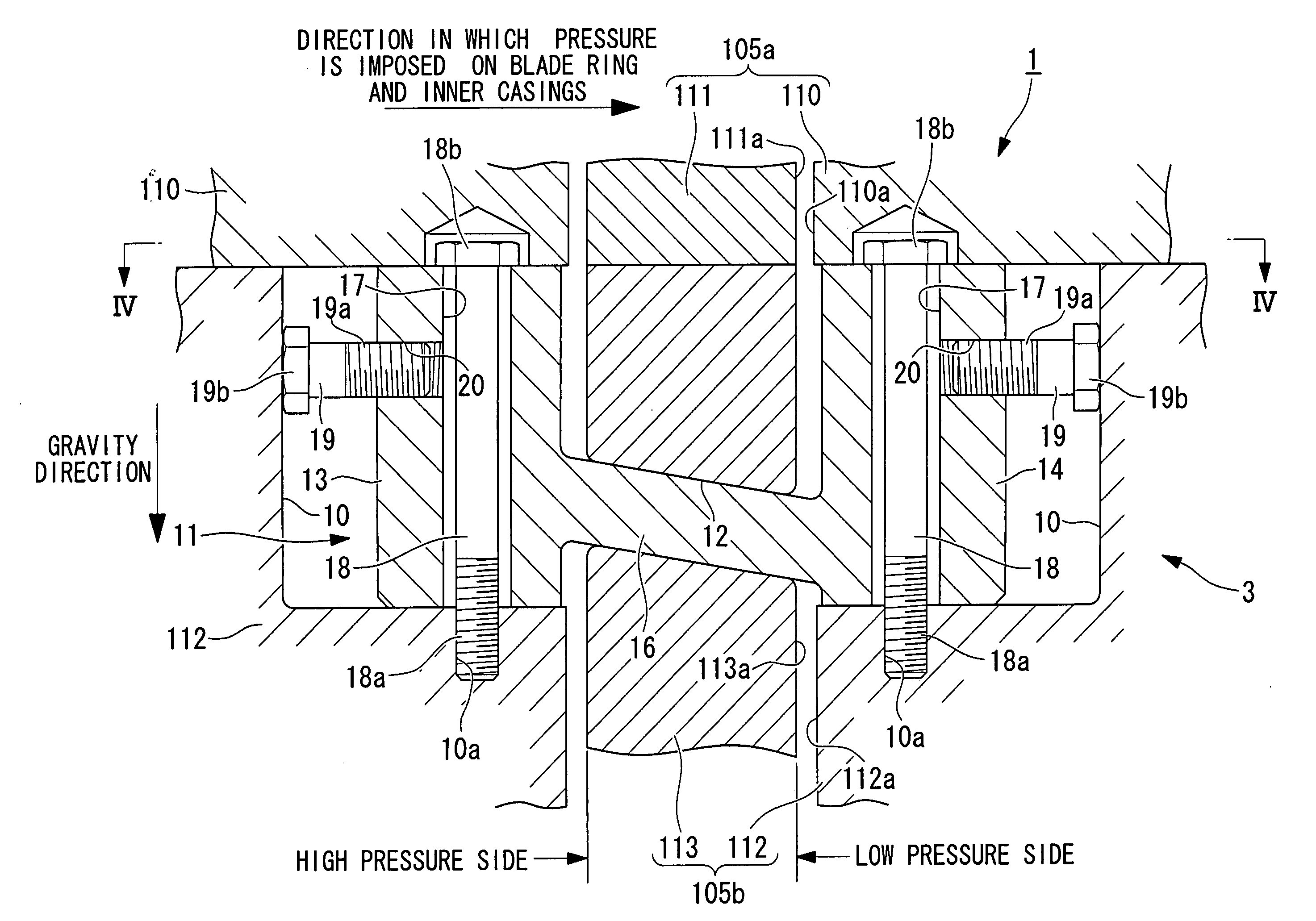
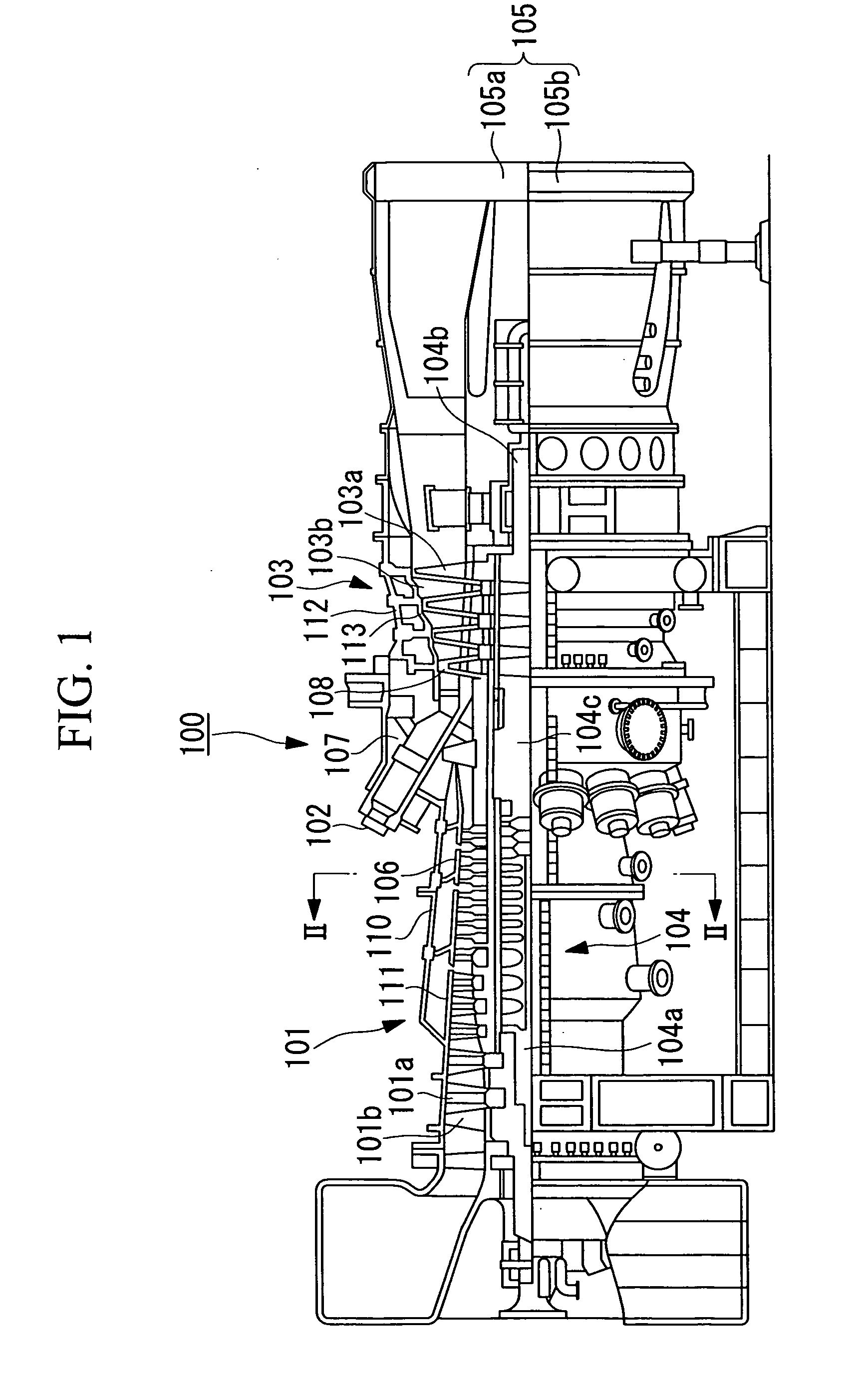
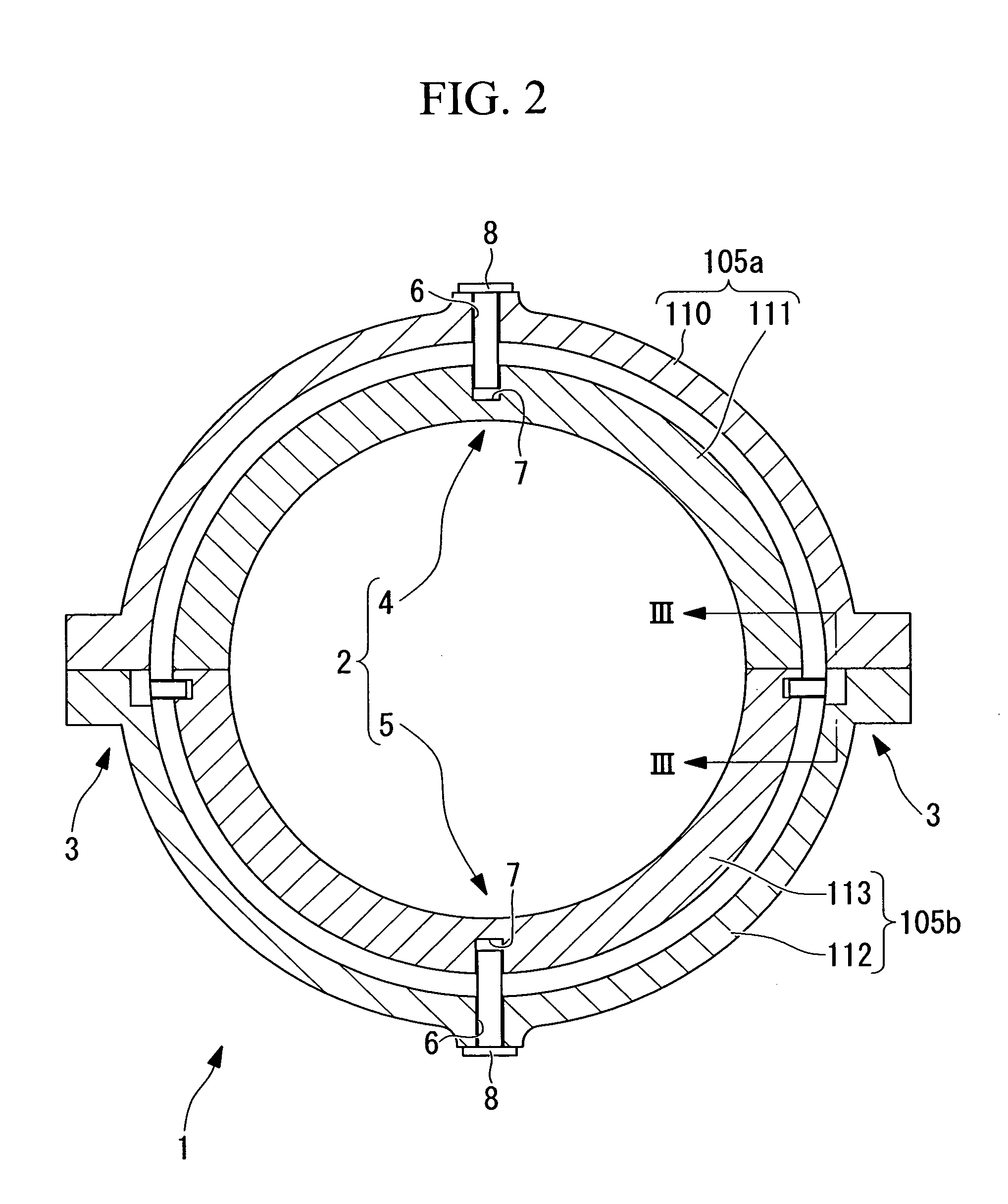
[0029]FIG. 1 is a schematic structural view showing a concrete example in which a centering mechanism 1 according to this embodiment is applied to a turbine (hereinafter referred to as “gas turbine”) 100. FIG. 2 is a cross-sectional view along the line II-II shown in FIG. 1. FIG. 3 is a cross-sectional view along the line III-III shown in FIG. 2. FIG. 4 is a cross-sectional view along the line IV-IV shown in FIG. 3. FIG. 5 is a perspective view of a key constituting a vertical-direction positioning unit.

[0030]As shown in FIG. 1, the gas turbine (rotary machine) 100 includes, as main components, a compressor 101 which compresses air taken in from outside, combustors 102 which are supplied with the air compressed by the compressor 101 and fuel and which generate combustion gas, and a turbine 103 which is rotated by the combustion gas generated i...


PUM

PropertyMeasurementUnit
friction angleaaaaaaaaaa
pressureaaaaaaaaaa
thicknessaaaaaaaaaa

Abstract

The present invention provides a centering mechanism capable of improving the efficiency of centering work and reducing the work time and the cost. The centering mechanism centers an inner member located inside in a radial direction, with respect to an outer member arranged to surround the inner member in a circumferential direction, and includes a vertical-direction positioning unit which positions the inner member in a vertical direction in a non-stepwise manner.

Description

BACKGROUND OF THE INVENTION[0001]1. Field of the Invention[0002]The present invention relates to a centering mechanism that performs centering of an inner casing in a turbine or a blade ring in a rotary machine such as a compressor or a turbine.[0003]This application is based on Japanese Patent Application, Publication No. 2008-115720, the content of which is incorporated herein by reference.[0004]2. Description of Related Art[0005]Centering of an inner casing in a turbine or a blade ring in a rotary machine such as a compressor or a turbine is conventionally performed with the use of a pin in the horizontal direction and a key (liner) in the vertical direction (see Japanese Unexamined Patent Application, Publication No. 2005-171783 (FIGS. 2 and 3), for example).[0006]In this case, for centering in the vertical direction, a key having a thickness larger than a planned value is made in advance, and is cut down to reduce the thickness to fit the actual inner casing or blade ring at th...

Claims


Application Information

Patent Timeline
Patent Type & Authority Applications(United States)
IPC IPC(8): B23P19/10
CPCF01D25/26Y10T29/53978F05D2230/64F05D2230/644
Inventor ICHIRYU, TAKU
Owner MITSUBISHI POWER LTD
Learn More