Manufacturing method for probe contact

a manufacturing method and contact technology, applied in the manufacture of contact parts, instruments, connection formation by deformation, etc., can solve the problems of uneven contact pressure over a plurality, affecting the dispersion of the fracturing position on the substrate, and the method of fracturing the substrate for contact is prone to generate dispersion, etc., to achieve easy production, easy control, and high precision

Inactive Publication Date: 2010-03-04
YAMAICHI ELECTRONICS
View PDF4 Cites 4 Cited by
  • Summary
  • Abstract
  • Description
  • Claims
  • Application Information

AI Technical Summary

Benefits of technology

[0013]By the configuration of the present invention, when the end portion of the substrate of the probe contact is fractured and cut off, the fracturing position thereof can be easily controlled with high precision, so that the tip of the lead can be stably formed as an appropriate resilient armature. Therefore, a probe contact corresponding effectively to the electrodes developing into those with a minute pitch for the terminals of the test substance for energizing test can be easily produced with a low cost.

Problems solved by technology

However, this method may give damage such as deformation to the lead when the substrate is fractured.
However, the method of fracturing the substrate for contact is prone to generate dispersion with respect to the fracturing position of the front face side at the end of the substrate after it is fractured.
Furthermore, dispersion of the fracturing position on the substrate is affected by the practice of compressing when it is fractured.
Dispersion of the fracturing position is directly connected to dispersion of the length of the resilient armature, and is greatly affected to the quantity of resilient bending and rubber elasticity.
Additionally, meandering of the fracturing position causes unevenness of the contact pressure over a plurality of leads.
If the fracturing position is out of the proper region and does not clear the product specification in manufacturing of the probe contact, the probe contact comes to be defective and production yield thereof is decreased.
Such dispersion of the fracturing position including meandering is a problem that comes to be obvious as the above-mentioned electrodes are developing into those with a minute pitch and thereby the lead thereof comes to be fine.

Method used


Image

  • Manufacturing method for probe contact
  • Manufacturing method for probe contact
  • Manufacturing method for probe contact

Examples


Embodiment Construction

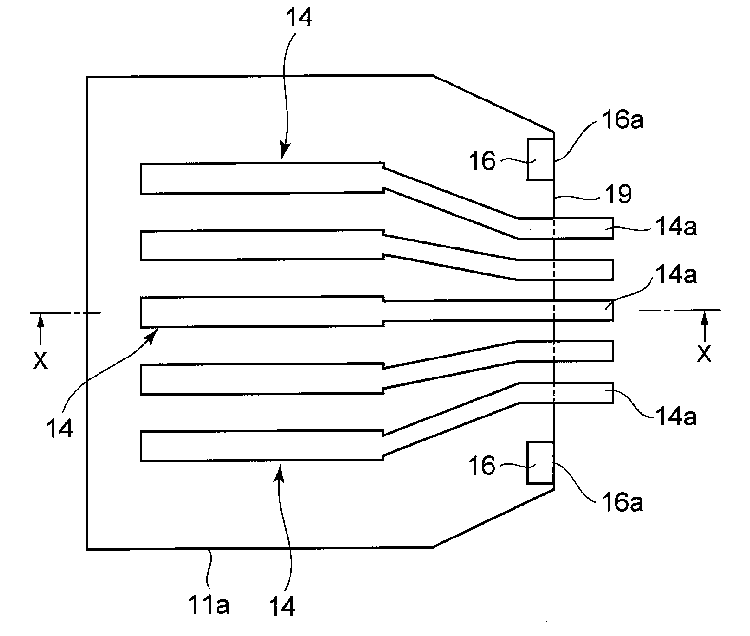
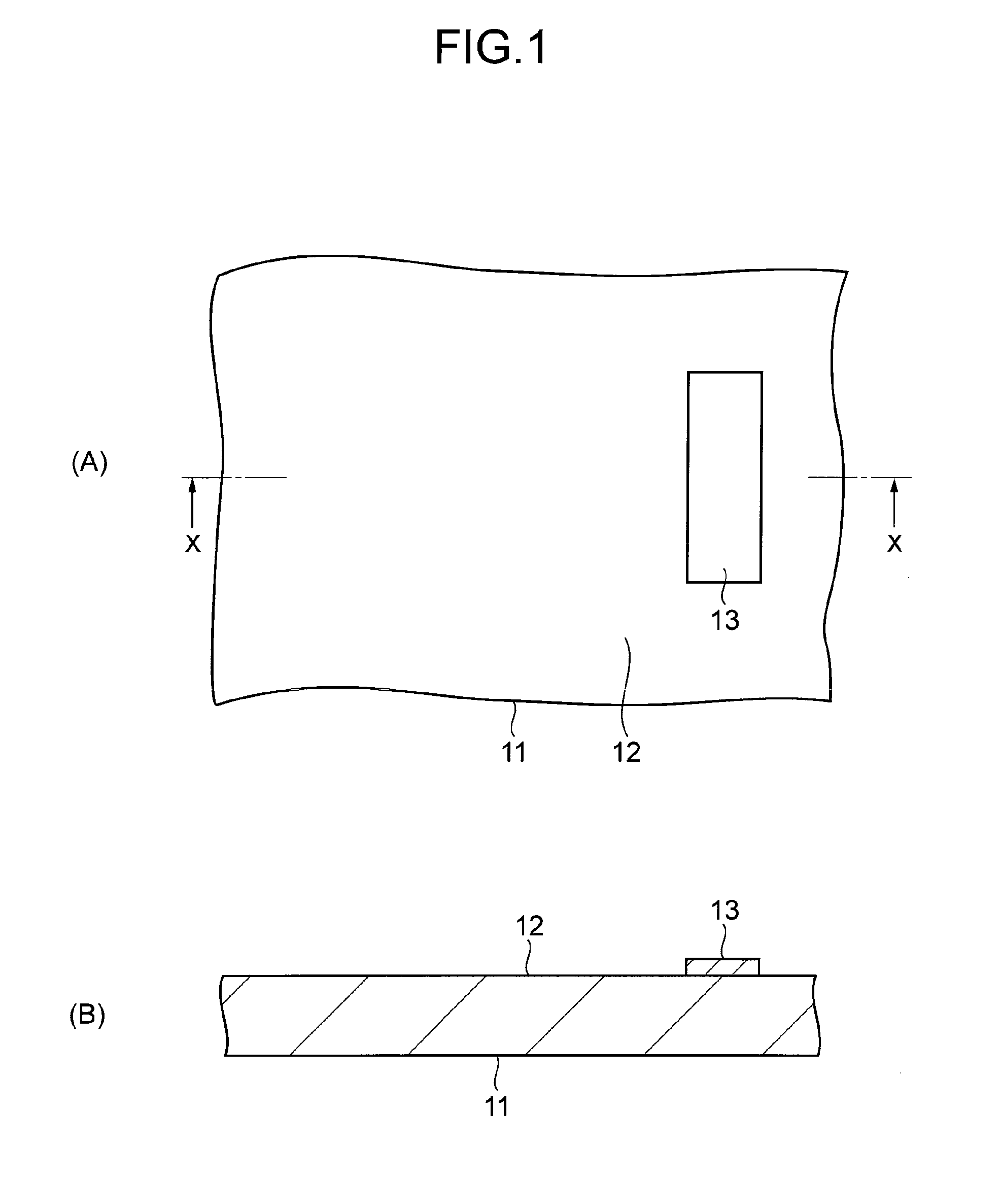
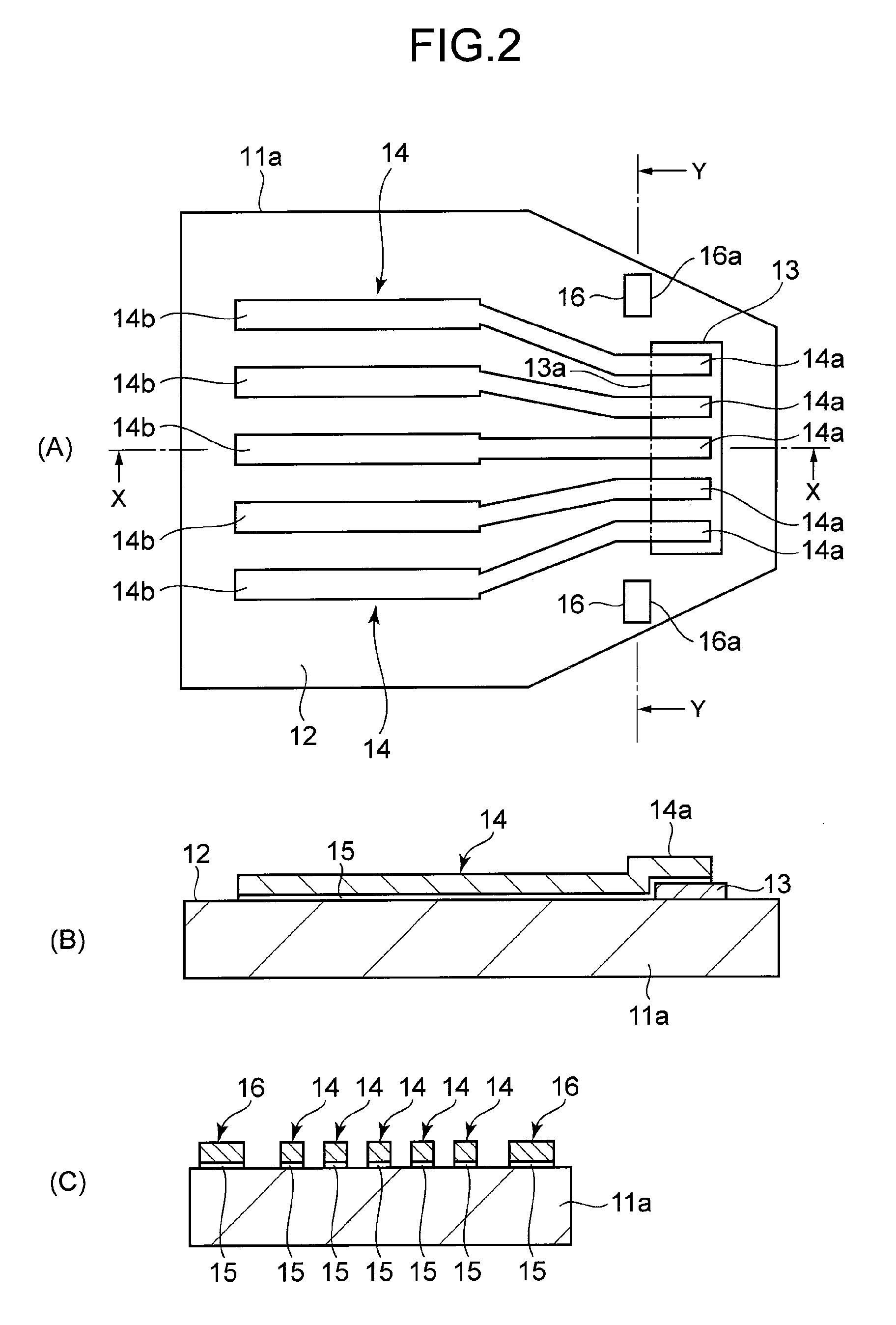
[0025]Some embodiment of the present invention will be explained hereafter referring to the drawings. The same or similar portions together are denoted by the common sign and overlapping explanation will be omitted. Figures are so schematic that the ratio of measures etc. is different from the actual one. FIG. 1 to FIG. 6 are plan views and cross sectional views thereof showing each manufacturing process of one example of the manufacturing method for a probe contact relating to the present invention. Here, each cross sectional view is the one observed from the direction of the X-X arrow or the Y-Y arrow described in the corresponding plan view.

[0026]First of all, as shown in FIG. 1, a sacrifice layer 13 is formed on a plain front face 12 of a substrate 11 for fabricating a plurality of probe contact products by one sheet. Here, the substrate 11 is constituted of a material capable of brittle fracture with the thickness of several hundred μm, such as zirconia, alumina, glass, or sili...


PUM

PropertyMeasurementUnit
thicknessaaaaaaaaaa
thicknessaaaaaaaaaa
thicknessaaaaaaaaaa

Abstract

To make the fracturing position controlled conveniently with high precision when the substrate end of the probe contact is fractured and cut off.
By compressing the front face of the substrate end portion with the pushing member, brittle fracture is generated on the substrate along the carved groove, and the substrate end portion is cut off from the substrate. The fracturing position in the above-mentioned fracturing is controlled so as to be along the fracturing position whose extension puts thereon the stress concentrating ends of two fracturing control structures. Here, the fracturing control structure is located with high positional precision on the front face of the substrate through the alignment technique of photolithography. In this way, resilient armatures constituted of the tips projected from the fracturing position coming to be the end of the substrate 11a can be stably formed with high precision.

Description

TECHNICAL FIELD[0001]The present invention relates to a manufacturing method for a probe contact to carry out the energizing test for semiconductor devices, display panels, etc., and particularly relates to a manufacturing method for a probe contact capable of corresponding to electrodes developing into those with a minute pitch of a test substance without difficulty and effectively.BACKGROUND ART[0002]Recently, electrodes for terminals arranged in a test substance such as electronic device substrates for semiconductor integrated circuits and flat panel displays (FPD), or circuit substrates have a tendency to have the pitch thereof becoming minute more and more. Therefore, a probe contact having a minute pitch corresponding to the pitch of these electrodes is required for the side of the energizing test equipment in the energizing test of these electronic devices and circuit substrates.[0003]As a method for manufacturing a probe contact having a minute pitch, the manufacturing metho...

Claims


Application Information

Patent Timeline
Patent Type & Authority Applications(United States)
IPC IPC(8): H01R43/16
CPCG01R1/06716G01R3/00Y10T29/49204Y10T29/4979Y10T29/49121Y10T29/49218G01R1/073
Inventor SUZUKI, TAKEYUKIUJIKE, RYOWAKABAYASHI, YOSHINORI
Owner YAMAICHI ELECTRONICS
Why Eureka
Try Eureka