
Variable Speed Supercharger With Electric Power Generation

a supercharger and electric power technology, applied in the direction of machines/engines, positive displacement liquid engines, gearing, etc., can solve the problems of low boost ratio and insufficient torque to achieve the desired engine torque

Active Publication Date: 2010-03-04
THE TIMKEN CO
View PDF16 Cites 21 Cited by
  • Summary
  • Abstract
  • Description
  • Claims
  • Application Information

AI Technical Summary

Benefits of technology

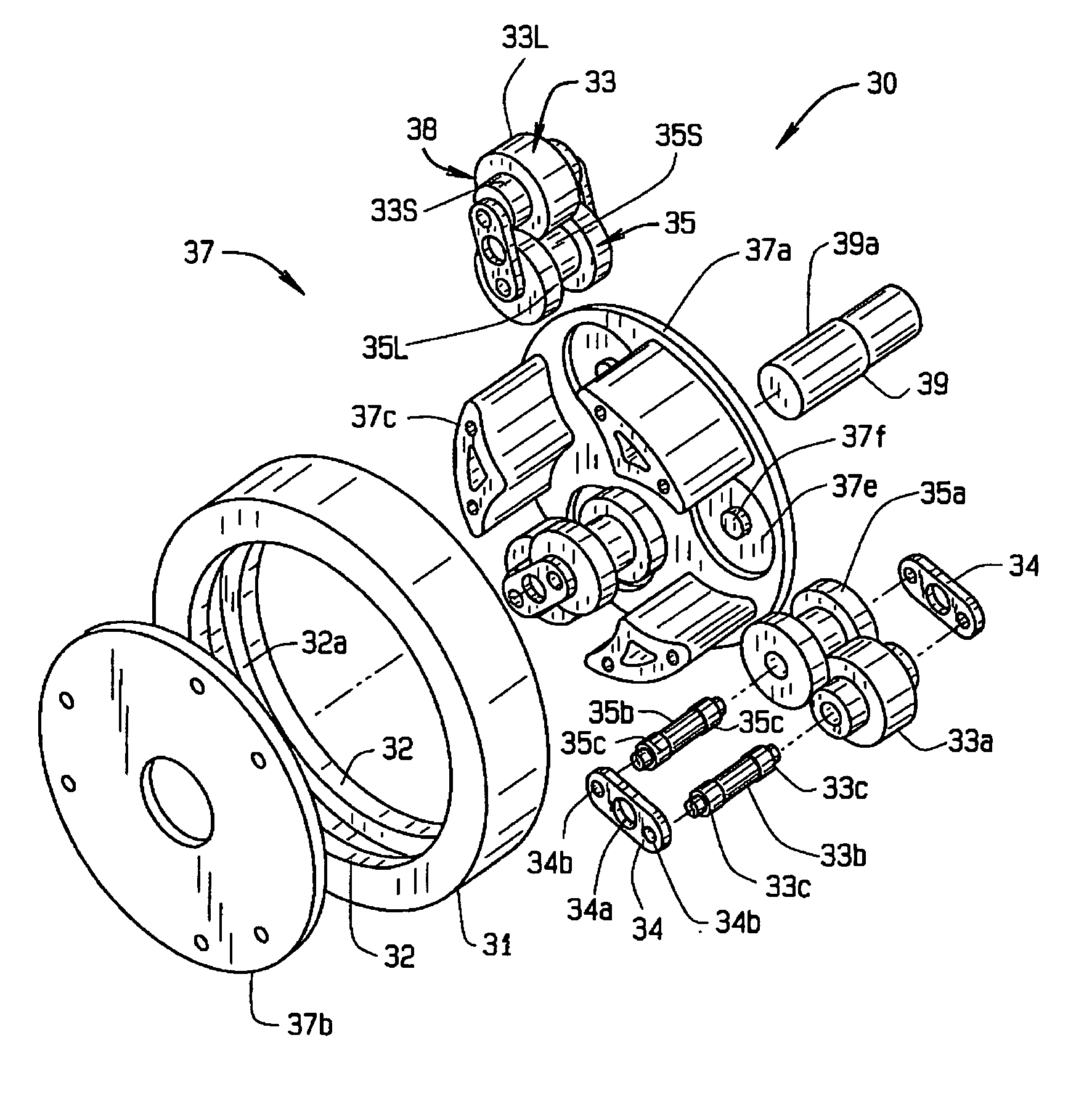
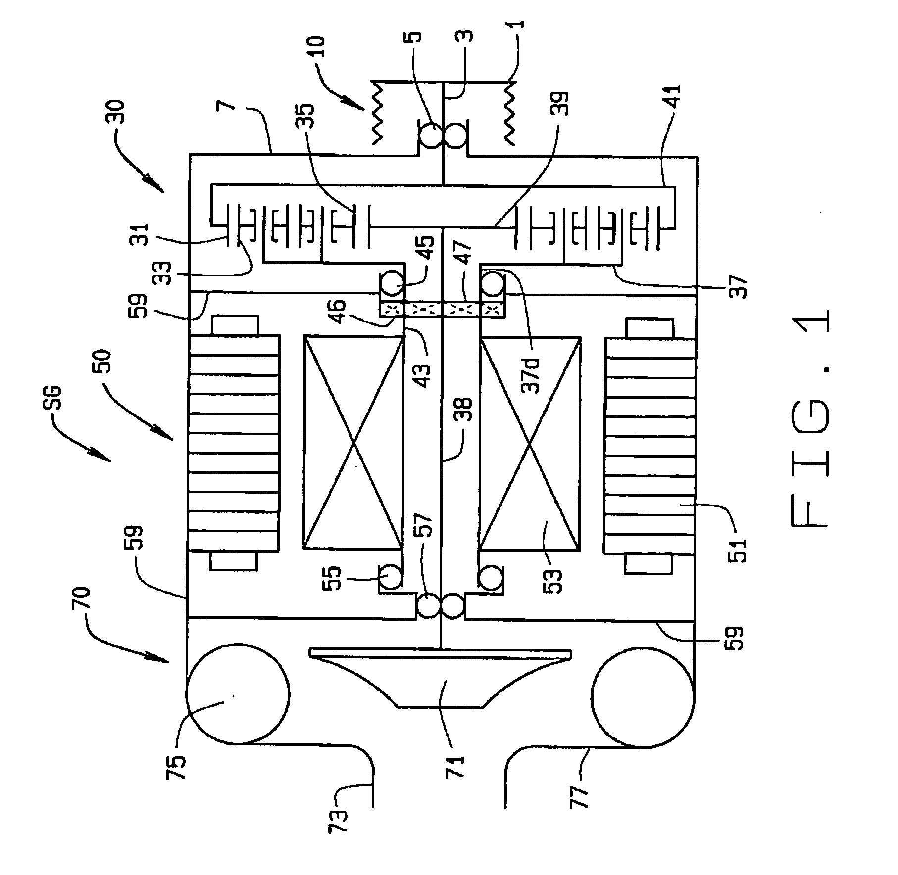
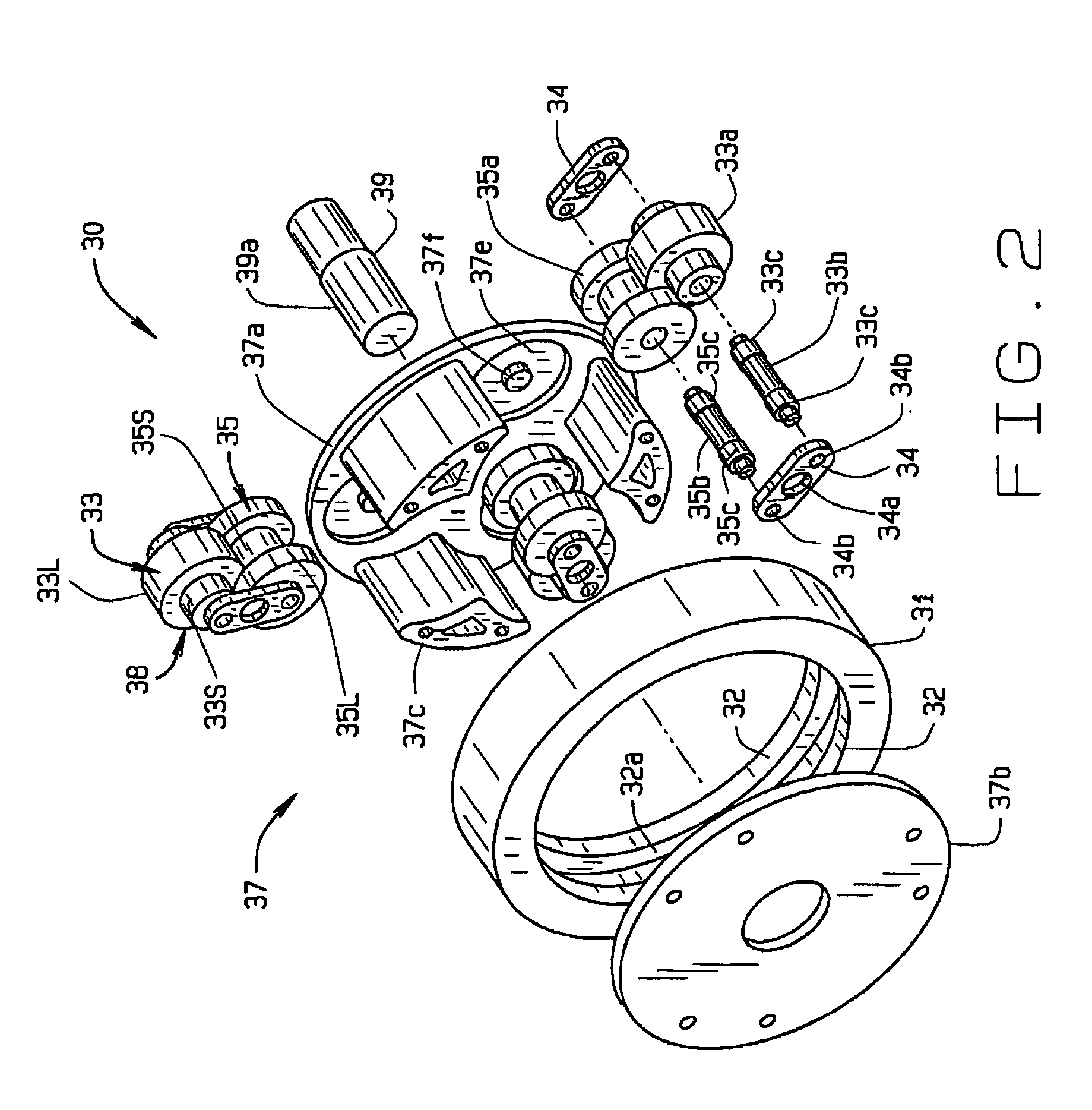
[0006]An electro-mechanical variable speed supercharger combines a supercharger and an alternator in a compact unit to provide fully controllable boost-on-demand supercharging operation across the entire engine speed range and to offer intelligent electric power generation to maintain the battery's state of charge (SOC).
[0008]In the first mode (called the boosting mode), the electric machine rotates in the opposite direction to the drive pulley. The electric machine is in the motoring state applying shaft torque in the same direction as the speed of rotation. The electric machine draws electric power from a battery system; the friction drive combines the electric power from the electric machine with mechanical power from the drive pulley and delivers the power to the compressor. In the boosting mode, the friction drive provides an increasing speed ratio between the impeller and pulley; thereby boosting engine power as required. Even at relatively low engine speeds, the impeller is able to operate at a higher speed to boost engine torque.

Problems solved by technology

At low engine speed, the boost ratio is low and insufficient to provide desired engine torque.

Method used


Image

  • Variable Speed Supercharger With Electric Power Generation
  • Variable Speed Supercharger With Electric Power Generation
  • Variable Speed Supercharger With Electric Power Generation

Examples


Embodiment Construction

[0015]The following detailed description illustrates the invention by way of example and not by way of limitation. This description will clearly enable one skilled in the art to make and use the invention, and describes several embodiments, adaptations, variations, alternatives and uses of the invention, including what we presently believe is the best mode of carrying out the invention. Additionally, it is to be understood that the invention is not limited in its application to the details of construction and the arrangements of components set forth in the following description or illustrated in the drawings. The invention is capable of other embodiments and of being practiced or being carried out in various ways. Also, it is to be understood that the phraseology and terminology used herein is for the purpose of description and should not be regarded as limiting.

[0016]An electro-mechanical variable speed supercharger-generator unit SG is shown schematically or diagrammatically in FI...


PUM


Abstract

A supercharger for boosting intake manifold pressure in an internal combustion engine and producing electrical energy comprises an input shaft (3), a electric machine (50) including a stator (51) and a rotor (53), a compressor (70) including an impeller (71), and a planetary transmission (30) located between the input shaft (3) and the rotor (53) of the electric machine (50) and the impeller (71) of the compressor (70), all such that the input shaft 3 can drive both the impeller (71) and the rotor (53), or the rotor (53) and input shaft (3) can drive the impeller (71). The planetary transmission (30) includes an outer ring (31) operatively coupled to the input shaft (3), a sun member (39) operatively coupled to the impeller (71), planetary clusters (38) located between the outer ring (31) and sun member (39), and a carrier (37) operatively coupled to the planet clusters (38) and the rotor (53). Each planetary cluster (38) comprises an inner roller (35) and an outer roller (33).

Description

RELATED APPLICATIONS[0001]This application claims priority to U.S. Provisional Application No. 60 / 839,598 filed Aug. 23, 2006, which is entitled “Variable Speed Supercharger With Electric Power Generation, and which is incorporated herein by reference.BACKGROUND ART[0002]The increasing demand on fuel efficiency requires engines to provide higher output without increasing total piston displacement and / or weight. One effective way to achieve this is through forced induction systems to boost the intake pressures. More air and thus more fuel can be added to each cylinder. Consequently, more mechanical power is generated from each explosion in each cylinder.[0003]There are two basic types of forced induction systems. One is referred to as supercharger and the other is referred to as turbocharger. The difference between the two systems is their source of energy. Turbochargers are powered by the mass-flow of exhaust gases driving a turbine; superchargers are powered mechanically by belt or...

Claims


Application Information

Patent Timeline
IPC IPC(8): F02B39/04F16H13/08
CPCF02B33/40F02B39/04F16H13/06F04D13/028F16H3/724F02B39/10F04D25/028F05D2220/40F02B33/34F16H13/08F02B61/06
Inventor AI, XIAOLANREMBOSKI, DONALD
Owner THE TIMKEN CO
Learn More