
Ventilator With Controlled Purge Function

a technology of purge function and ventilator, which is applied in the direction of respirator, inhalator, etc., can solve the problems of difficult to continuously accurate measurement, harsh sensor environment, and ventilator circuit, so as to prevent purging and improve the purging

Inactive Publication Date: 2010-03-04
TYCO HEALTHCARE GRP LP
View PDF105 Cites 175 Cited by
  • Summary
  • Abstract
  • Description
  • Claims
  • Application Information

AI Technical Summary

Benefits of technology

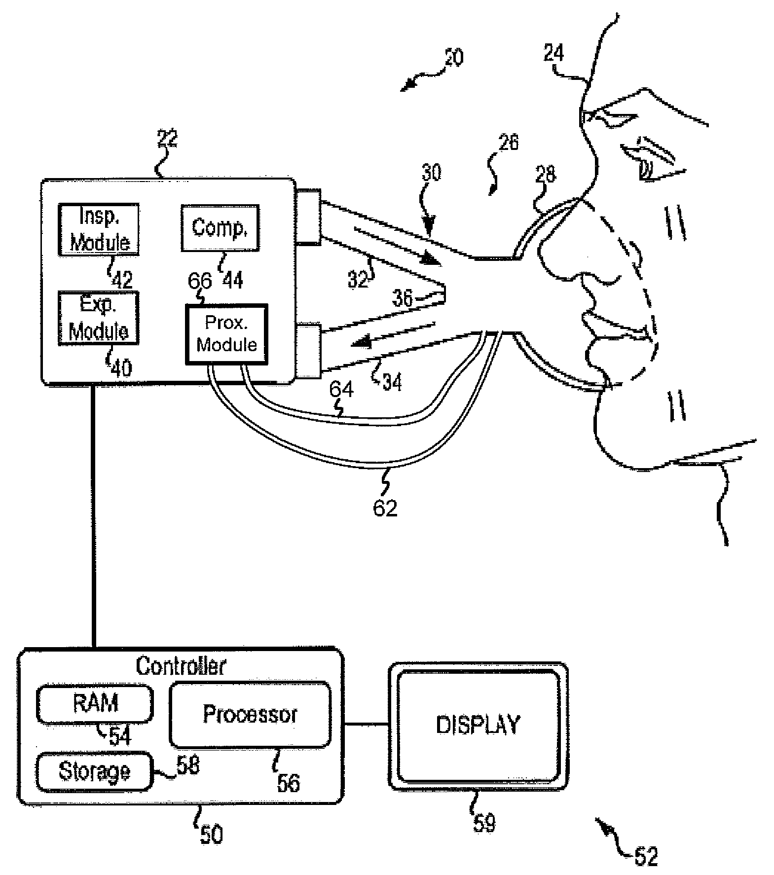
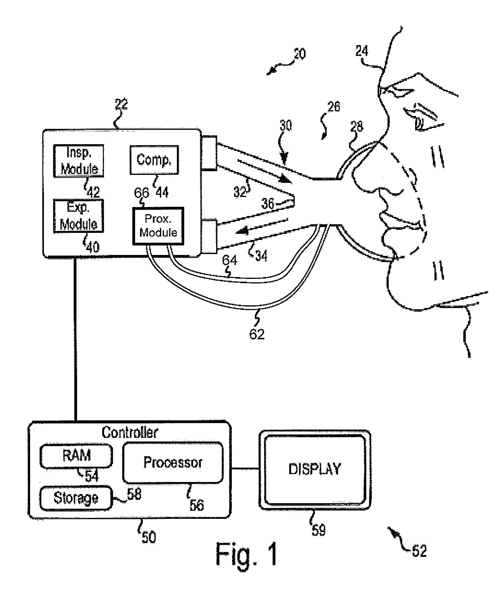
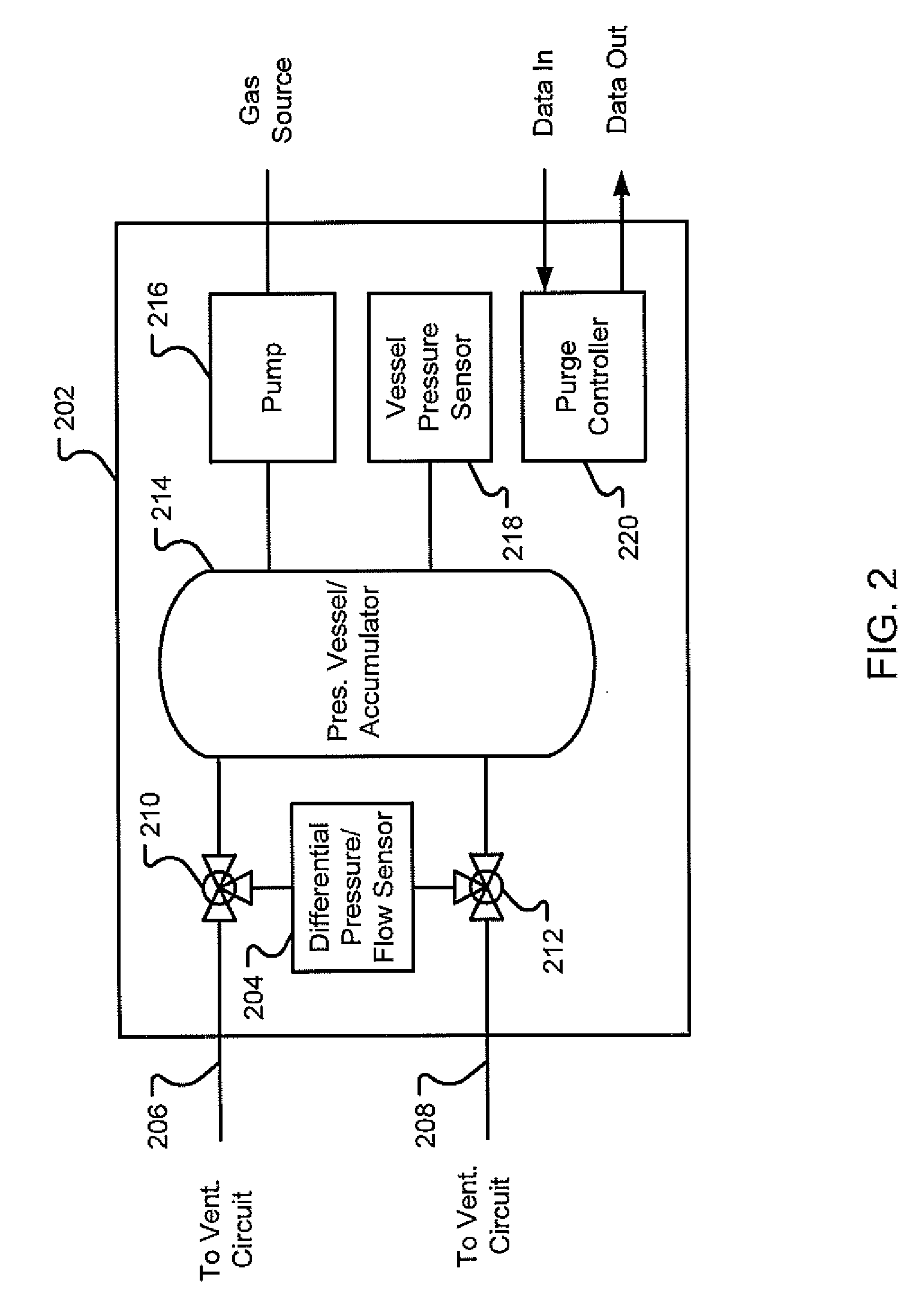
[0004]This disclosure describes systems and methods for purging narrow diameter sensor tubing, occasionally referred to as “sensor lines”, in a ventilation system. Among other aspects, this disclosure describes ventilator systems in which the purging of sensor lines is synchronized to a ventilator-generated signal. Through the signal, purging is prevented from occurring during inspiration and during events such as ventilation maneuvers. Purging is further improved by monitoring the pressure of the gas used to purge the sensor lines in order to prevent purges being performed when the pressure is too high or too low.
[0006]For example, in some situations, it may be desirable to purge only during a patient exhalation. This acts to prevent or help prevent an inhalation of material expelled during the purge, and reduces the maximum inflation of the lungs which would occur if purging occurred at the end of inspiration when the lungs are at their peak inflation point. Furthermore, it can be desirable, and in some cases preferred to begin to purge not at the very beginning of exhalation, but later in exhalation when the lungs are partially deflated.
[0007]In the current Puritan Bennett 840 ventilator, the shortest exhalation phase is about two hundred milliseconds (200 ms). Especially in such cases, fine control over when the purge of the proximal flow sensor package starts is desirable. Since the ventilator is in control of when the exhalation valve opens and the exhalation phase begins, it can know this point in time sooner and with higher precision than does a proximal flow sensor package. Use of a hardware “purge enable” signal sourced at the ventilator to control the start of purging can help guarantee precision timing for purging.
[0008]In some embodiments of the systems and methods described herein, the possibility of a poorly timed purge may be reduced or eliminated by adding a “purge enable” hardware signal sourced by the ventilator and sent to the microprocessor on the proximal flow sensor package. In some embodiments, coupling this hardware signal with suitable software commands reduces the possibility of an ill-timed purge, and results in negligible patient impact. Such additional software commands may include one or more commands directed to (1) setting target accumulator pressures and / or pressure tolerances, (2) setting a purge delay time; (3) providing low pressure (PEEP) information to the proximal sensor package; (4) recording and / or transmitting purge duration; and (5) establishing purge abort criteria.

Problems solved by technology

However, the ventilator circuit and particularly the patient wye is a challenging environment to make continuously accurate measurements.
The harsh environment for the sensor is caused, at least in part, by the condensations resulting from the passage of humidified gas through the system as well as secretions emanating from the patient.
Over time, the condensate material can enter the sensor tubes and / or block its ports and subsequently jeopardize the functioning of the sensor.
There are times during ventilator operation that it would be undesirable to purge.
In some embodiments, coupling this hardware signal with suitable software commands reduces the possibility of an ill-timed purge, and results in negligible patient impact.

Method used


Image

  • Ventilator With Controlled Purge Function
  • Ventilator With Controlled Purge Function
  • Ventilator With Controlled Purge Function

Examples


Embodiment Construction

[0022]Although the techniques introduced above and discussed in detail below may be implemented for a variety of medical devices, the present disclosure will discuss the implementation of these techniques in the context of a medical ventilator for use in providing ventilation support to a human patient. The reader will understand that the technology described in the context of a medical ventilator for human patients could be adapted for use with other systems such as ventilators for non-human patients and general gas transport systems in which sensor tubes in challenging environments may require periodic or occasional purging.

[0023]Medical ventilators are used to provide a breathing gas to a patient who may otherwise be unable to breathe sufficiently. In modern medical facilities, pressurized air and oxygen sources are often available from wall outlets. Accordingly, ventilators may provide pressure regulating valves (or regulators) connected to centralized sources of pressurized air...


PUM


Abstract

This disclosure describes systems and methods for purging narrow diameter sensor tubing in a ventilation system. Among other aspects, this disclosure describes ventilation systems in which a sensor tube purge module utilizes a ventilator-generated signal to synchronize the purging of sensor tubes with the delivery of respiratory therapy. Through the signal, purging is prevented from occurring during inspiration and during events such as ventilation maneuvers. Purging may be further improved by monitoring the pressure of the gas used to purge the sensor tubes in order to prevent purges being performed when the pressure is too high or too low. One way to achieve this is by purging the sensor tubes using gas discharged from an accumulator, in which the pressure in the accumulator is monitored and controlled by the sensor tube purging module.

Description

RELATED APPLICATIONS[0001]This application claims the benefit of U.S. Provisional Application No. 61 / 094,377 filed Sep. 4, 2008 and U.S. Provisional Application No. 61 / 169,976 filed Apr. 16, 2009, which applications are hereby incorporated herein by reference.INTRODUCTION[0002]Medical ventilators may determine when a patient takes a breath in order to synchronize the operation of the ventilator with the natural breathing of the patient. In some instances, detection of the onset of inhalation and / or exhalation may be used to trigger one or more actions on the part of the ventilator.[0003]In order to accurately detect the onset of inhalation and / or exhalation, and / or obtain a more accurate measurement of inspiratory and expiratory flow / volume, a flow or pressure sensor may be located close to the patient. For example, to achieve accurate and timely non-invasive signal measurements, differential-pressure flow transducers may be placed at the patient wye proximal to the patient. However...

Claims


Application Information

Patent Timeline
IPC IPC(8): A61M16/00
CPCA61M16/0858A61M16/00A61M16/0063A61M2016/0027A61M16/0833A61M16/085A61M16/0051A61M16/024
Inventor GRABOI, DANIEL G.
Owner TYCO HEALTHCARE GRP LP
Learn More