Roll Unit Dipped in Surface Treatment Liquid

a surface treatment and roll shaft technology, applied in the direction of sealing devices, rigid support of the bearing unit, manufacturing tools, etc., can solve the problems of high corrosiveness of the above treatment solution, severe abrasion and corrosion of the bearing, and treatment liquid infiltrating into the bearing, etc., to prevent the abrasion and corrosion of the roll shaft, and simple replacement of the bearing box

Inactive Publication Date: 2010-03-04
JX NIPPON MINING& METALS CORP
View PDF4 Cites 16 Cited by
  • Summary
  • Abstract
  • Description
  • Claims
  • Application Information

AI Technical Summary

Benefits of technology

[0013]The present invention was devised in view of the foregoing problems, and relates to a roll unit to be used in electrochemical surface treatments such as roughening treatment, rust prevention treatment, and oxidized surface treatment (blackening treatment) to be continuously performed on a surface of a rolled copper foil or an electrolytic copper foil, and in particular relat

Problems solved by technology

Solutions such as copper sulfate and chromic acid are used in the electrochemical surface treatment, and the foregoing treatment solutions are highly corrosive.
With the rolls used under the foregoing circumstances, there is a problem in that the treatment liquid will infiltrate into the bearing, and the bearing in particular is subject to severe abrasion and corrosion.
Thus, devices have been made for filling grease into the bearing of the roll so as to inhibit the abrasion and to facilitate the replacement of the roll bearing, but such devices were i

Method used


Image

  • Roll Unit Dipped in Surface Treatment Liquid
  • Roll Unit Dipped in Surface Treatment Liquid
  • Roll Unit Dipped in Surface Treatment Liquid

Examples


Embodiment Construction

[0027]A representative example of the present invention is now explained with reference to the attached drawings. Incidentally, the following explanation illustrates a preferred embodiment, and is not intended to limit the present invention in any way. Thus, modifications and other examples and modes included in the technical concept of the present invention provided in the claims and specification are all covered by this invention.

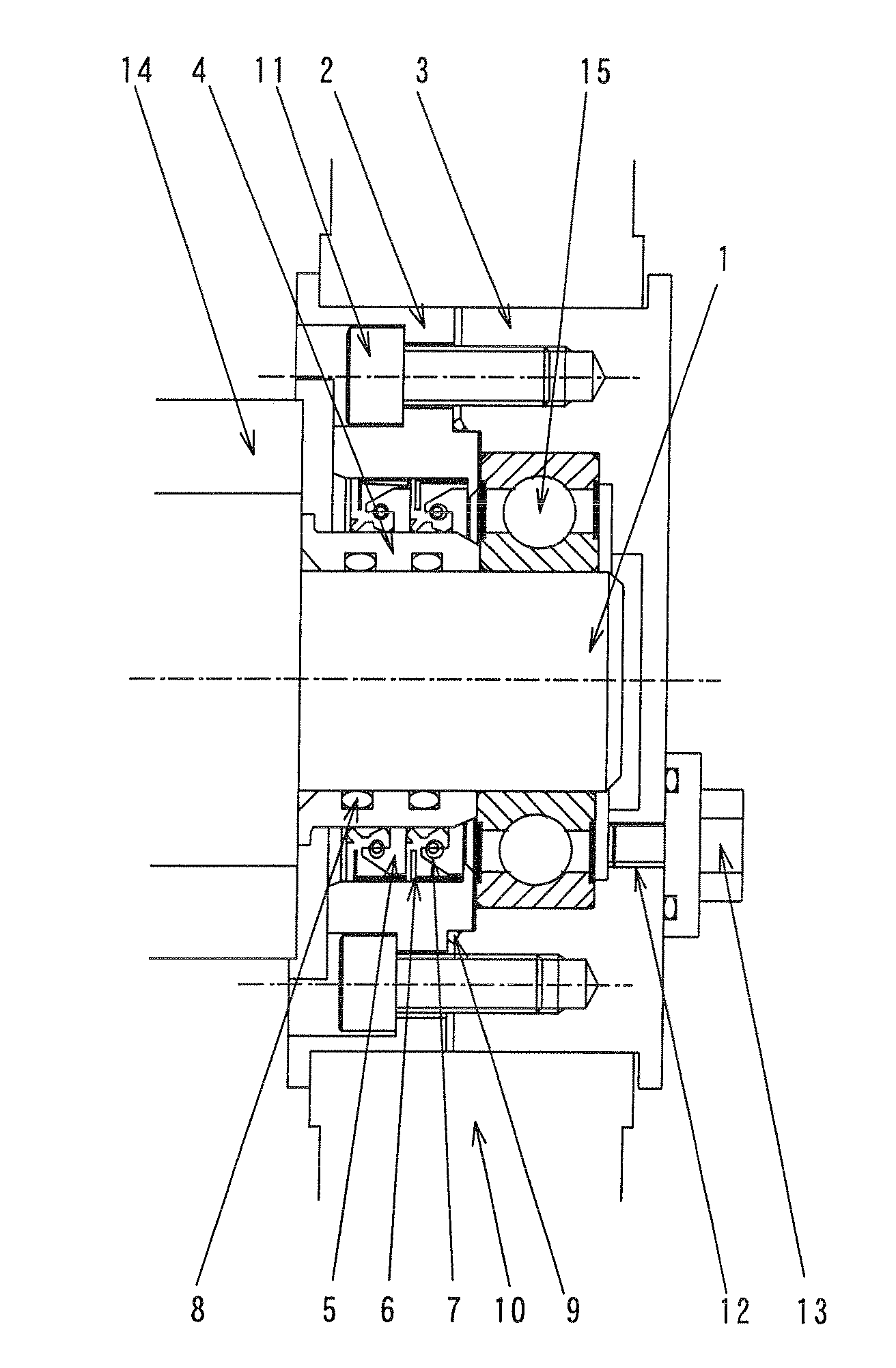
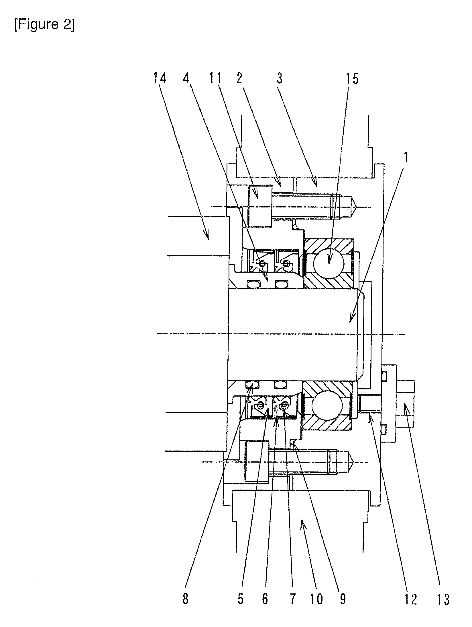
[0028]With the roll unit to be dipped in a surface treatment liquid according to the present invention, a bearing box for housing a roll shaft 1 is configured from two bearing boxes that are divisible. One of the bearing boxes is configured from a roll-side bearing box 2 arranged on a roll main body-side and the other bearing box is configured from a shaft end-side bearing box 3 arranged on the shaft end-side of the roll. The bearing box is usually configured from heat-resistant vinyl chloride. Other materials may also be used so as long as they are heat-...


PUM


Abstract

Provided is a roll unit to be dipped in a surface treatment liquid of a copper foil, wherein a bearing box for housing a roil shaft is configured from two bearing boxes that are divisible, one of the bearing boxes is configured from a roll-side bearing box arranged on a roll main body-side and the other bearing box is configured from a shaft end-side bearing box arranged on the shaft end-side of the roll, a shaft sleeve covering an outer periphery of the roll shaft is provided in the roll-side bearing box and an oil seal is provided along an outer periphery of the shaft sleeve, and a bearing for rotatably supporting the shaft is disposed in the shaft end-side bearing box. Specifically, the present invention provides a roll unit to be used in electrochemical surface treatments such as roughening treatment, rust prevention treatment, and oxidized surface treatment (blackening treatment) to be continuously performed on a surface of a rolled copper foil or an electrolytic copper foil, and which is capable of inhibiting the abrasion and corrosion of the roll shaft of such roll unit by controlling the corrosion caused by the infiltration of the treatment liquid, and which enables the simple replacement of the bearing box, bearing, and other components.

Description

TECHNICAL FIELD[0001]The present invention relates to a roll unit to be used in electrochemical surface treatments such as roughening treatment, rust prevention treatment, and oxidized surface treatment (blackening treatment) to be continuously performed on a surface of a rolled copper foil or an electrolytic copper foil, and in particular relates to a roll unit to be dipped in a surface treatment liquid.BACKGROUND ART[0002]In recent years, copper foil is being widely used in the manufacture of electronic components, wiring substrates and the like.[0003]Generally speaking, an electrolytic copper foil is manufactured by using a rotating metal cathode drum and an insoluble metal anode (positive electrode) arranged at a position that is roughly at the lower half of the cathode drum and which surrounds the periphery of such cathode drum, electrodepositing copper on the cathode drum by flowing copper electrolyte between the cathode drum and the anode and applying a potential therebetween...

Claims


Application Information

Patent Timeline
IPC IPC(8): C25D17/00F16C13/00C25D7/06C25D17/06F16C13/02F16J15/3212F16J15/3232F16J15/3252
CPCC25D7/0614C25D7/0657C25D17/00C25D17/004F16C33/76F16C35/04F16C13/02
Inventor SATO, HARUO
Owner JX NIPPON MINING& METALS CORP
Why Eureka
Try Eureka