Stabilizer device with wheeled guide arm

a stabilizer device and guide arm technology, which is applied in the direction of interconnection systems, vehicle springs, resilient suspensions, etc., can solve the problems of reducing the service life of the stabilizer device. , to achieve the effect of reducing bending and preventing torque bias

Inactive Publication Date: 2010-03-04
ZF FRIEDRICHSHAFEN AG
View PDF14 Cites 4 Cited by
  • Summary
  • Abstract
  • Description
  • Claims
  • Application Information

AI Technical Summary

Benefits of technology

[0011]A rigid connection of the end of the anti-roll bar with the end of the steering rod—thus managing without joints—is first of all advantageous in this connection inasmuch as the constructionally expensive and typically susceptible, articulated connection of the wheel steering rod upon the end of the anti-roll bar is completely dispensed with. Besides, in this way, one can make possible a direct conversion completely free of play of the stroke motion of the control arm into a corresponding rotary motion of the anti-roll bar, with which the desirable immediate response of the anti-roll bar also improves.
[0026]According to a particularly preferred embodiment of the invention, it is finally provided that the wheel steering rod is a hinged tie bar or a diagonal strut of a wheel suspension. Although the invention is basically used in conjunction with the various control arm shapes, such as transversal control arms, oblique control arms, or longitudinal control arms, the use of the invention in conjunction with a hinged tie bar or with a diagonal strut is particularly advantageous inasmuch as, when working with a tension or diagonal strut, the acute angle between the swing axis of the strut and the rotation axis of the anti-roll bar is particularly small. That results in a particularly reduced bending as well as direct transmission of the anti-roll bar during the compensation movement of the wheel steering rod. Furthermore, in this embodiment of the invention, the anti-roll bar can be arranged without any structural space problems in a particular space-saving manner in the particular forward or rear area of the axle mount in which the traction or diagonal strut is also articulated.

Problems solved by technology

The connection type of the chassis side end of the wheel guide steering rod to the stabilizer end in these known stabilizer devices, however, is comparatively expensive.
Since first of all the stabilizer and the stabilizer bearing are not designed for the absorption and feeding of wheel guide forces into the vehicle chassis, it is necessary to enter into considerable compromises in the solutions known from the state of the art with relation to force introduction and vibration absorption.
There is another fact that makes it more difficult to couple the wheel guide steering rod to the stabilizer end; the rotation axis of the stabilizer extends in direction transversal to that of the vehicle, while the rotation axes of wheel guide steering rods, for example, the rotation axes of the hinged tie bars or diagonal struts considered here, generally extend at an acute angle with respect to the direction transversal to the vehicle.

Method used


Image

  • Stabilizer device with wheeled guide arm
  • Stabilizer device with wheeled guide arm

Examples


Embodiment Construction

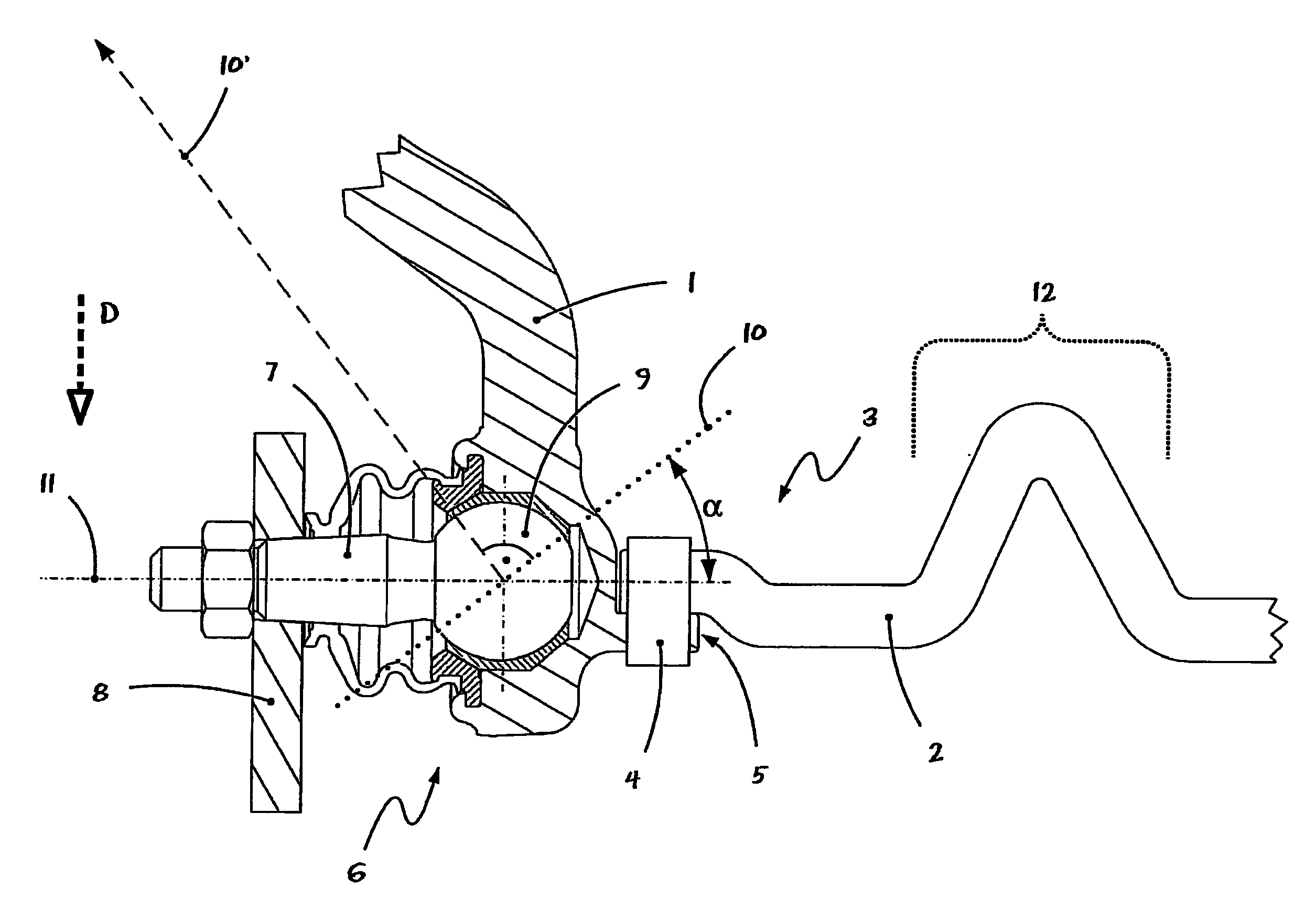
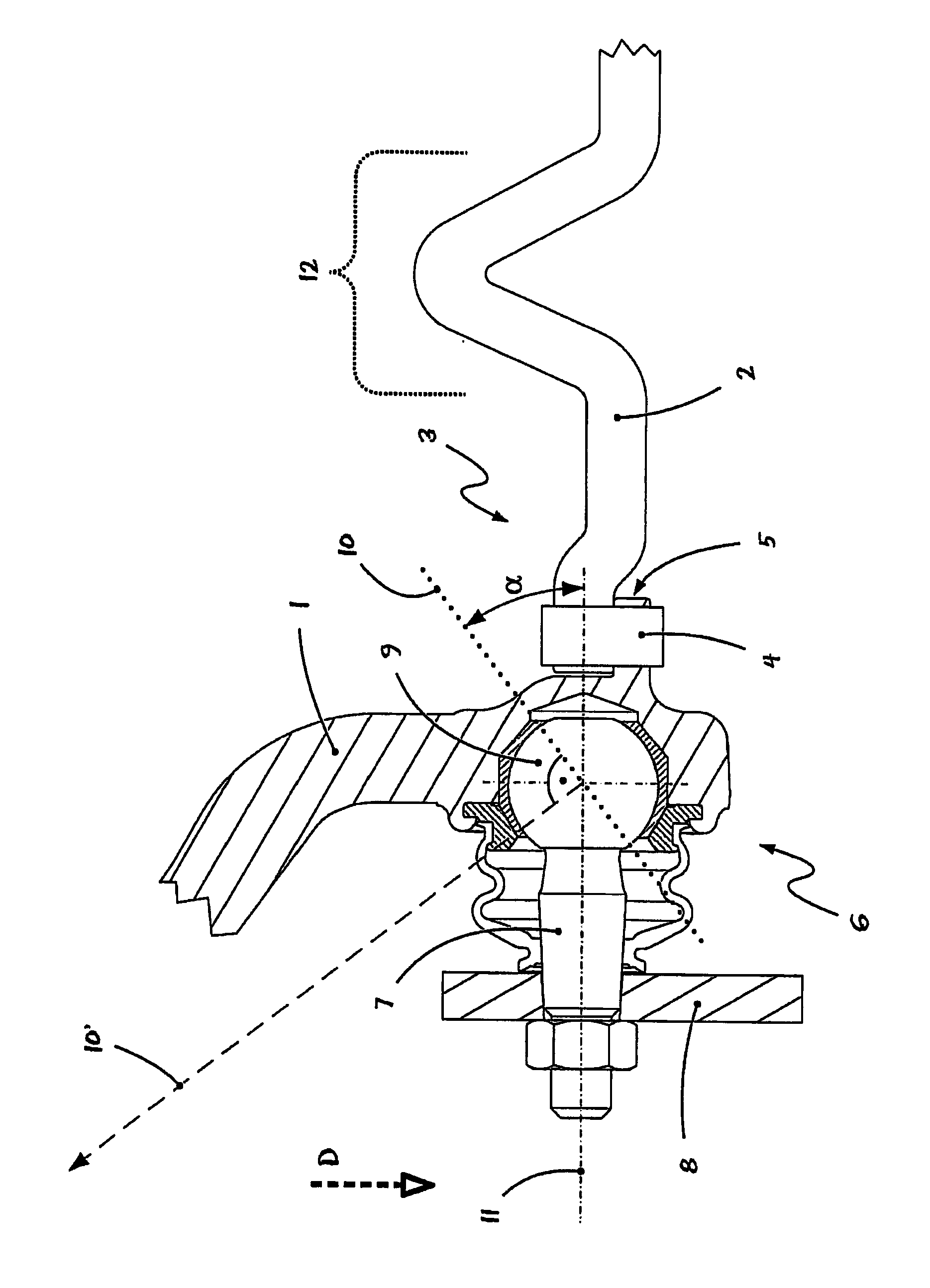
[0029]The FIGURE shows the connection between a wheel steering rod 1 and the pertinent end 3 of an anti-roll bar 2 in an embodiment of a anti-roll bar device according to this invention, looking at it from the underside of the vehicle. The FIGURE illustrates the left end of the anti-roll bar with relation to the direction of movement as well as chassis side end of the pertinent wheel steering rod 1 of the left wheel. The direction of motion of the associated vehicle here, with relation to the drawing, is downward, as indicated by the broken line of arrow D.

[0030]In the FIGURE, we first of all recognize the vehicle-related left end area 3 of the massively shaped anti-roll bar 3 of the vehicle; as well as the chassis side end area of a likewise only partly illustrated wheel steering rod 1, which actually involves a hinged tie bar of the wheel suspension of one of the left wheels of a motor vehicle.

[0031]The end 3 of anti-roll bar 1, illustrated in the FIGURE, is rigidly connected here...


PUM


Abstract

An anti-roll bar device of an axle of a motor vehicle. The axle has an anti-roll bar (2) and, for each wheel, at least one steering rod (1). The chassis articulation (6) of the steering rod (1) is connected with an end (3) of the anti-roll bar (2), while the compensation movement of the steering rod (1) causes a twisting actuation of the (1) anti-roll bar (2). The anti-roll bar device is distinguished by the fact that the anti-roll bar (2) is rigidly connected with the chassis side end of the steering rod (1). The anti-roll bar arrangement facilitates constructively simple and sturdy articulation of the steering rod directly on the anti-roll bar as well as on the vehicle chassis or the axle mount. Furthermore, the assembly and installation of the anti-roll bar is simplified and the required structural space, weight and cost of the anti-roll bar are improved.

Description

[0001]This application is a National Stage completion of PCT / DE2007 / 001911 filed Oct. 25, 2007, which claims priority from German patent application serial no. 10 2006 054 874.4 filed Nov. 20, 2006.FIELD OF THE INVENTION[0002]This invention relates to a stabilizer device for a vehicle axle with a roll stabilizer.BACKGROUND OF THE INVENTION[0003]Typical vehicle axles, where the roll stabilizer is actuated directly by a wheel guide steering rod connected with the roll stabilizer, for example, by a hinged tie bar or diagonal strut of the wheel suspension, are first of all advantageous inasmuch as one can thus achieve a stabilizer ratio of 1:1. In other words, this means that the wheel's compression movements—in contrast to what happens in the case of the traditional roll stabilizers with pendulum support articulation—are converted into a corresponding torsion movement of the stabilizer not only proportionately but also in each case to the full extent. In such directly actuated stabiliz...

Claims


Application Information

Patent Timeline
Patent Type & Authority Applications(United States)
IPC IPC(8): B60G7/02B60G21/055
CPCB60G7/005B60G7/02B60G21/0551B60G2206/427B60G2202/135B60G2204/1224B60G2204/416B60G2200/18B60G21/05B60G21/055
Inventor BAUMER, BENJAMINHOFMANN, PETER
Owner ZF FRIEDRICHSHAFEN AG
Why Eureka
Try Eureka