Longitudinal Pulse Wave Array

a long-wave array and waveguide technology, applied in the field of acoustic pulse arrays, can solve the problems of bulky and cumbersome imaging systems, and achieve the effect of minimizing interference from outside the waveguide array and signal loss from the waveguide array

Active Publication Date: 2010-03-04
QUALCOMM INC
View PDF12 Cites 24 Cited by
  • Summary
  • Abstract
  • Description
  • Claims
  • Application Information

AI Technical Summary

Benefits of technology

[0007]An acoustic pulse array can be used to produce and send acoustic energy toward a target object where some of the energy is reflected by the target object. The reflected acoustic energy can be guided by the waveguide arrays to a detector, which can have an appropriate number of acoustic energy receiving elements. In doing so, crosstalk between waveguides in an array, signal loss from a waveguide array, and interference from outside the waveguide array can be minimized. At the detector, the acoustic energy can be converted to an electric signal, and that electric signal can be used to create a grayscale image.

Problems solved by technology

These techniques result in imaging systems that are bulky and cumbersome.

Method used


Image

  • Longitudinal Pulse Wave Array
  • Longitudinal Pulse Wave Array
  • Longitudinal Pulse Wave Array

Examples


Embodiment Construction

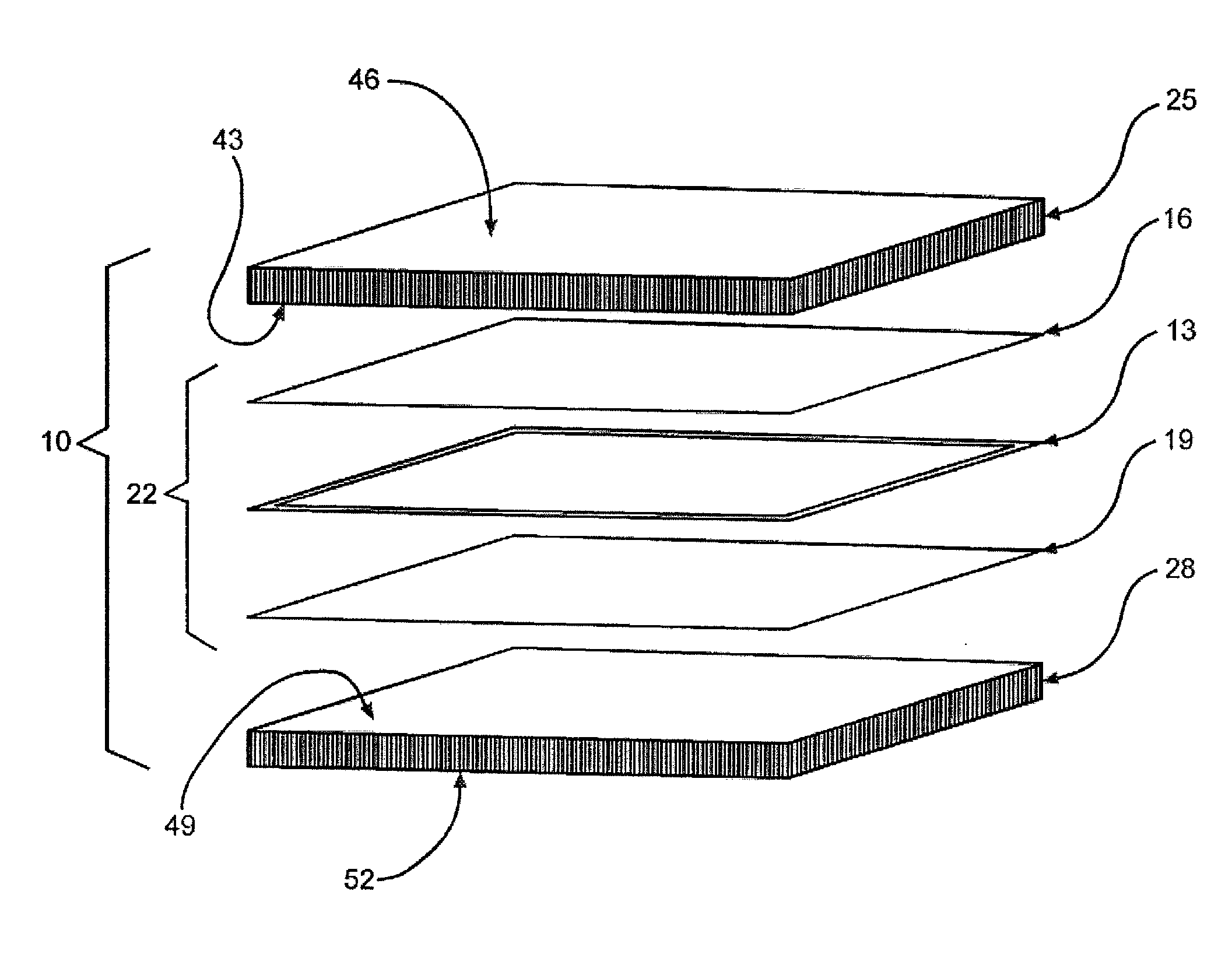
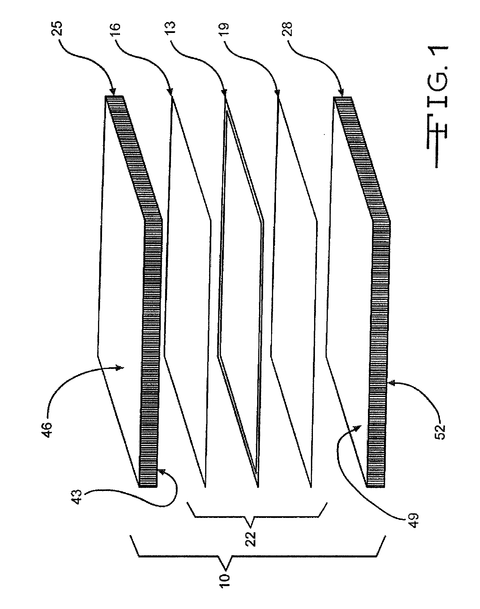
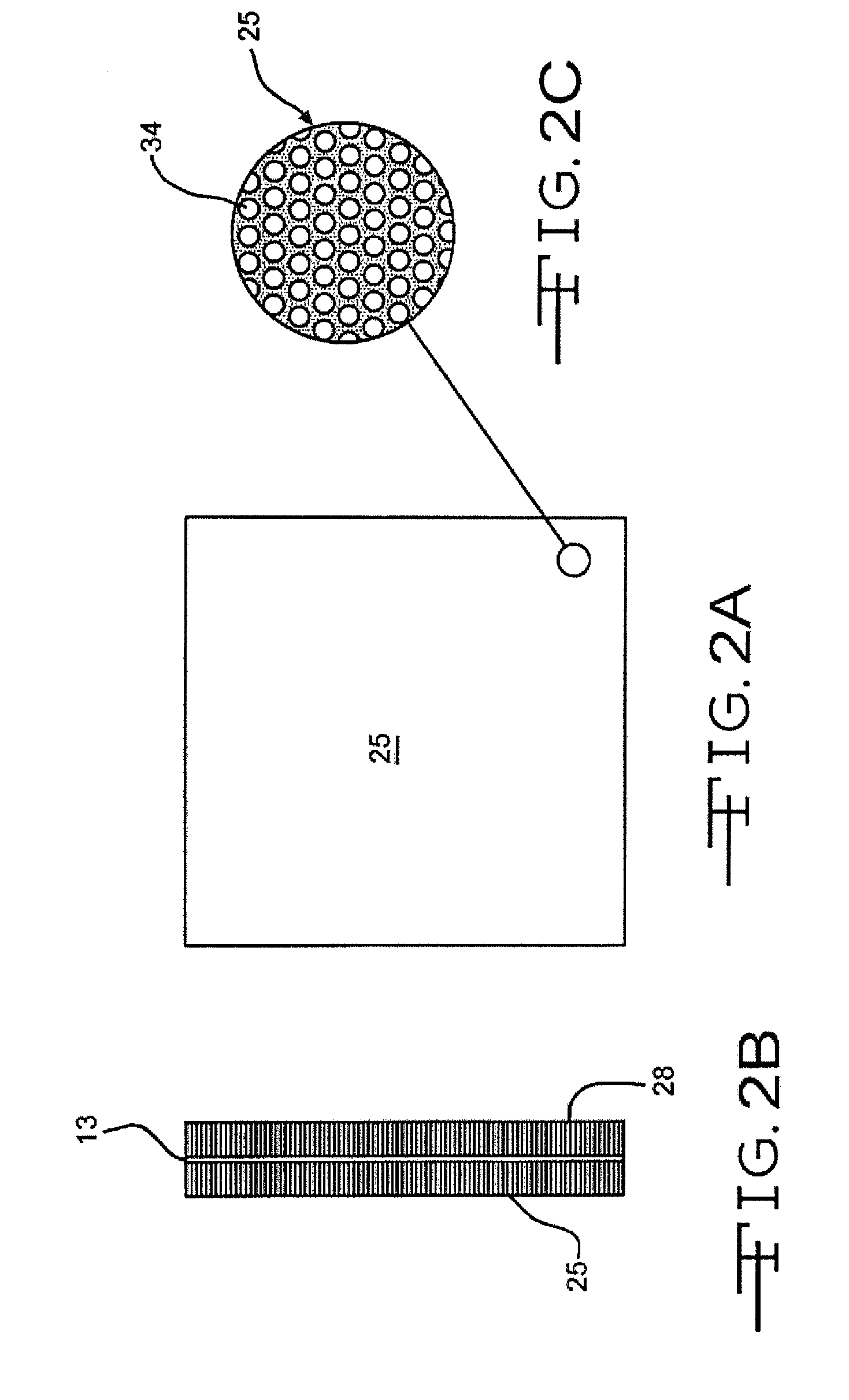
[0017]FIG. 1 shows components of an acoustic pulse array 10. A piezoelectric film 13 can be positioned between a first electrode 16 and a second electrode 19. The piezoelectric film 13 can be polyvinylidenefluoride (“PVDF”) polymer or polyvinylidene fluoride trifluoroethylene (“PVDF-TrFE”) and the electrodes 16, 19 can be metalized films of silver, indium-tin-oxide, chrome-gold, gold or some other conductive material. The electrodes 16, 19 can be vacuum sputtered to the piezoelectric film 13. The combination of the piezoelectric film 13 and the electrodes 16, 19 is referred to herein as acoustic wave generator (“AWG”) 22. The AWG 22 can be positioned between a first waveguide array 25 and a second waveguide array 28. Each waveguide array 25, 28 has the ability to convey acoustic energy from one side of the array to another side of the array. The waveguide arrays 25, 28 can be attached to the AWG 22 by an adhesive 30, such as epoxy or cyanoacrylate, residing between the waveguide arr...


PUM


Abstract

An acoustic pulse array is described. The pulse array can include a plane wave pulse generator having a first side from which a first wave emanates, and a second side from which a second wave emanates. A first waveguide array can be attached to the generator on the first side of the generator, and a second waveguide array can be attached to a second side of the generator. One or more of the waveguides can be attached to the generator so as to orient the waveguide to transmit wave pulses in a direction that is substantially perpendicular to the generator.

Description

CROSS-REFERENCE TO RELATED APPLICATIONS[0001]This application is a continuation-in-part of U.S. patent application Ser. No. 12 / 110,876, which was filed Apr. 28, 2008, and this application claims the benefit of priority to U.S. patent application Ser. No. 12 / 110,876. Ser. No. 12 / 110,876 is a continuation-in-part of U.S. patent application Ser. No. 11 / 754,131, which was filed on May 25, 2007. The 12 / 110,876 and 11 / 754,131 applications each claim the benefit of priority to U.S. provisional patent application Ser. No. 60 / 803,150, which was filed on May 25, 2006, and to U.S. provisional patent application Ser. No. 60 / 822,087, which was filed on Aug. 11, 2006 and to U.S. provisional patent application Ser. No. 60 / 914,203, which was filed on Apr. 26, 2007. This application claims the benefit of 60 / 803,150, 60 / 822,087, and 60 / 914,203.FIELD OF THE INVENTION[0002]This disclosure relates to an acoustic pulse array and, more specifically, to a flat panel acoustic pulse array employing piezoelec...

Claims


Application Information

Patent Timeline
Patent Type & Authority Applications(United States)
IPC IPC(8): H01L41/08H01L41/04
CPCA61B5/1172A61B8/08B06B1/0688G01N29/0654G01N2291/106G01N29/262G01N29/343G01N2291/02466G01N2291/044G01N29/2462
Inventor SCHNEIDER, JOHN K.KITCHENS, JACK C.
Owner QUALCOMM INC
Why Eureka
Try Eureka