Cell Arrangement for Feeding Electrical Loads such as Light Sources, Corresponding Circuit and Design Method

a technology for feeding electrical loads and light sources, applied in the direction of electroluminescent light sources, ac network voltage adjustment, electric lighting sources, etc., can solve the problems of reducing the useful life of light sources, complex solutions that require a current regulator for each cell, and inconvenient production, so as to avoid the presence of hf ripple and simple and inexpensive production

Inactive Publication Date: 2010-03-04
OSRAM GMBH
View PDF17 Cites 24 Cited by
  • Summary
  • Abstract
  • Description
  • Claims
  • Application Information

AI Technical Summary

Benefits of technology

[0008]The object of the present invention is to provide an improved arrangement which is simple and inexpensive to produce, while also giving the possibility of avoiding the presence of HF ripple in the signal supplied to electrical loads such as LED or LEDs and / or individually dimming each light source in a circuit arrangement including a plurality of cells connected to a single power source.

Problems solved by technology

Those solutions that require a current regulator for each cell are intrinsically complex and expensive, especially for low-cost applications.
Solutions resorting to decoupling networks may introduce HF ripple in the signal fed to light source or sources such as the LED or LEDs associated with the cell, which inevitably reduces the useful lifetime of these light sources.

Method used


Image

  • Cell Arrangement for Feeding Electrical Loads such as Light Sources, Corresponding Circuit and Design Method
  • Cell Arrangement for Feeding Electrical Loads such as Light Sources, Corresponding Circuit and Design Method
  • Cell Arrangement for Feeding Electrical Loads such as Light Sources, Corresponding Circuit and Design Method

Examples


Embodiment Construction

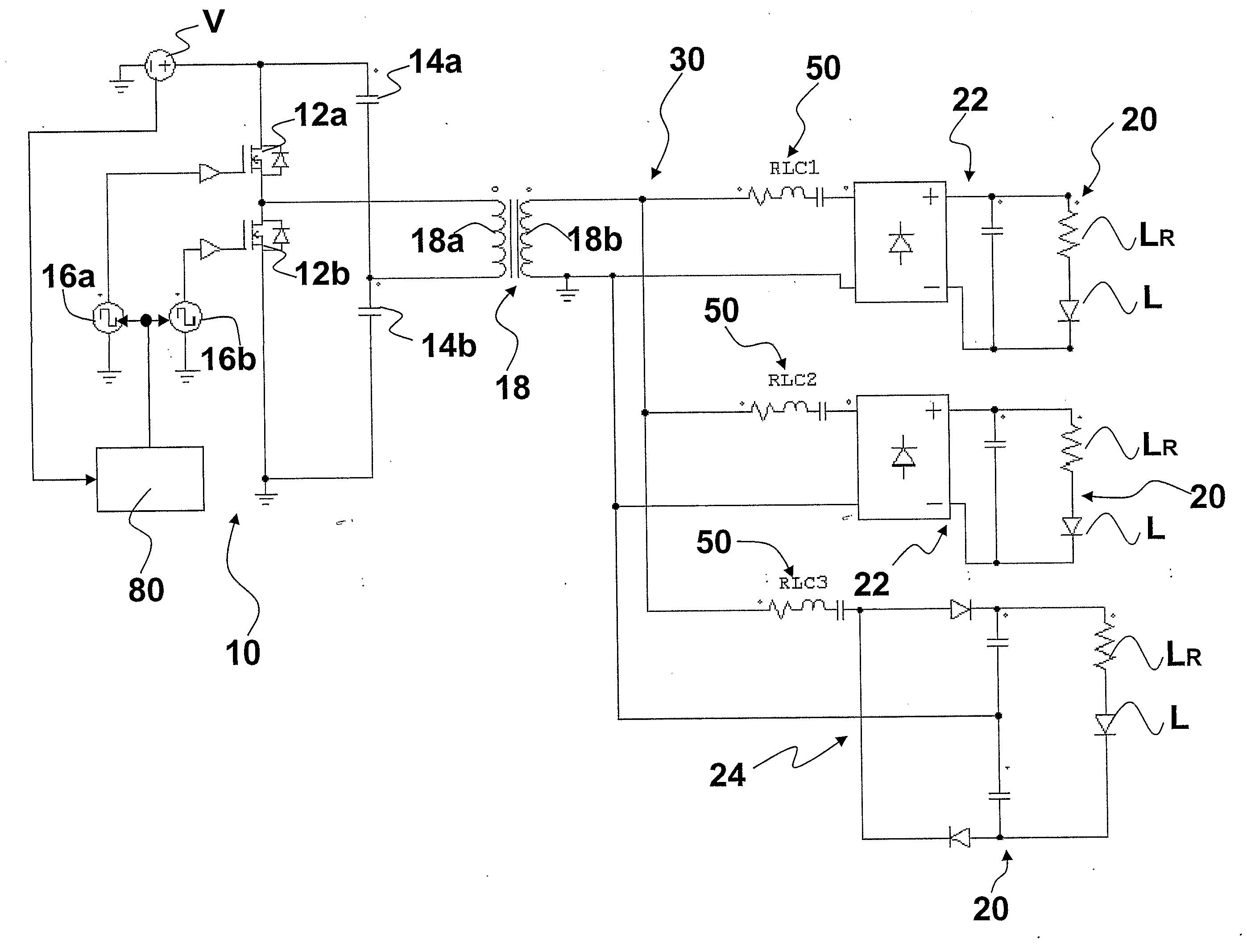
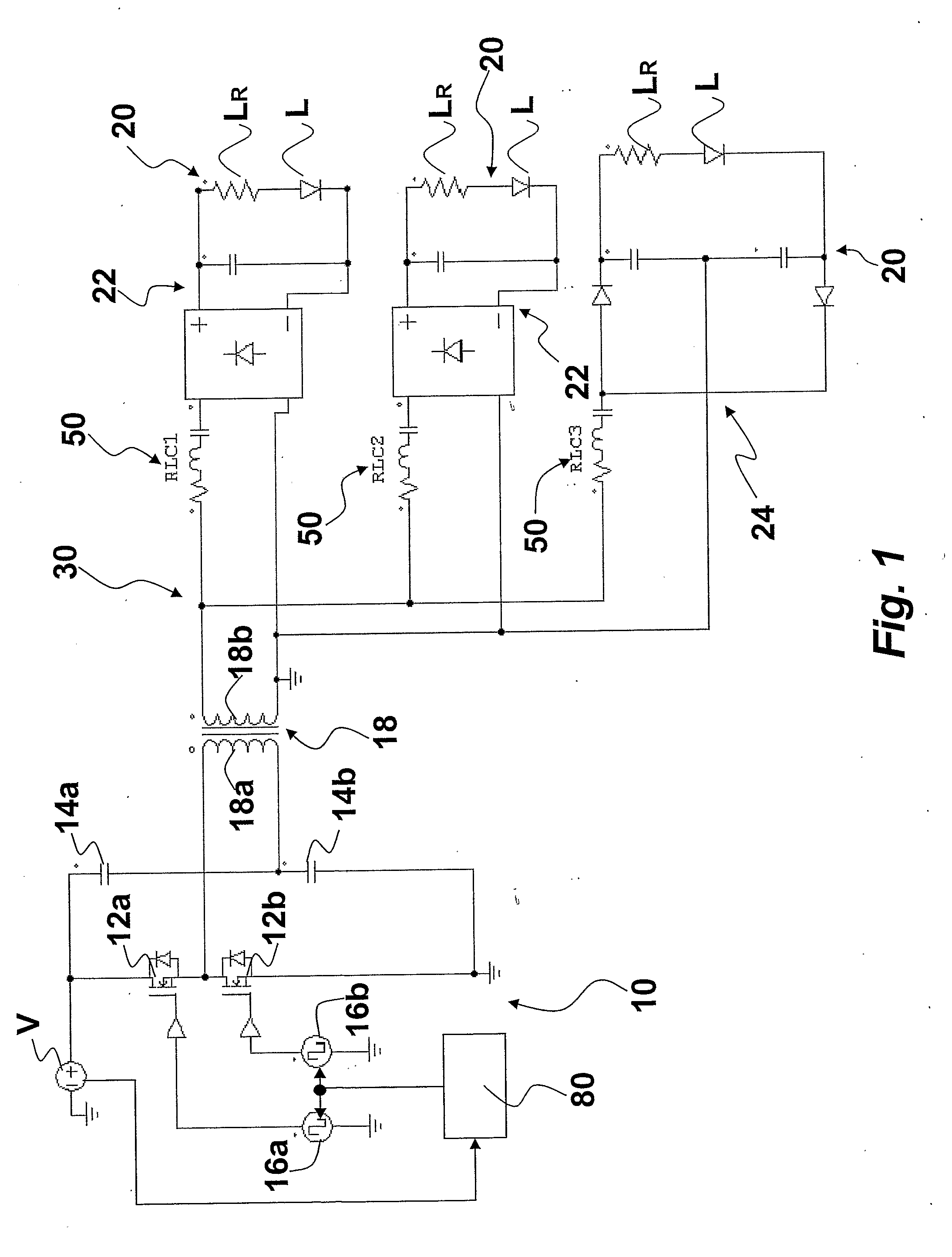
[0029]In general terms, FIGS. 1, 5, and 6 all refer to circuit arrangements including:

[0030]a power source 10, and

[0031]a plurality of cells 20 having associated respective electrical loads here represented by light sources such as semiconductor light sources, e.g. LEDs.

[0032]In the exemplary embodiments described herein, each cell 20 includes one or more light sources. Throughout this exemplary description, LEDs will be considered as exemplary of these light sources. LEDs such as High Flux (HF) LEDs are represented from the electrical viewpoint as the series connection of a diode L and an associated parasitic resistor LR.

[0033]The various LED cells 20 are connected to the power source 10 via a connecting structure 30 which essentially takes the form of a bus-like structure. The circuit arrangement described herein makes it possible to connect to the bus structure 30 several LED cells 20 which may be configured to draw different, fixed current values based on the specific requiremen...


PUM


Abstract

A circuit arrangement for driving electrical loads such as High Flux (HF) LEDs used as lighting sources. The circuit arrangement includes: a switched power source (10) providing a voltage signal switched with a switching frequency (Fsw) and having a given amplitude (Vout), and a plurality of cells (20) connected to the switched power source (10), wherein the LED cells (20) each include an LC decoupling impedance (50) for defining the intensity of the current flowing into the LED cell (30) from the switched power source (10). The LC decoupling impedance (50) includes LC components defining a resonance frequency (Fres) such that the switching frequency (Fsw) of the switched power source (10) is about one half the resonance frequency (Fres) of the LC decoupling impedance (50), whereby the average intensity of the current flowing into the cell is kept constant irrespective of the load on the LED cell (20).

Description

FIELD OF THE INVENTION [0001]The invention relates to feeding electrical loads such as light sources, e.g. Light Emitting Diodes (LEDs).[0002]The invention was devised by paying specific attention to its possible application to High Flux (HF) LEDs, which are being increasingly used as lighting sources. Reference to this preferred field of application is not however to be construed in a limiting sense of the scope of the invention.DESCRIPTION OF THE RELATED ART [0003]Within the context mentioned in the foregoing, the need frequently arises of paralleling several cells including light sources such as semiconductor light sources that require a constant current like LEDs.[0004]So far, this problem has been solved essentially in two ways, namely:[0005]by adding one current regulator for each individual cell, if the cells are fed from a voltage controlled source, or[0006]by associating to each cell some sort of decoupling network if the cells are fed via a High Frequency (HF) generator.[0...

Claims


Application Information

Patent Timeline
Patent Type & Authority Applications(United States)
IPC IPC(8): H05B37/02H02J3/00
CPCH05B33/0818H05B33/0815H05B45/10H05B45/382H05B45/39H05B45/46H05B45/37
Inventor ZANFORLIN, NICOLA
Owner OSRAM GMBH
Why Eureka
Try Eureka