Power regenerative converter

a technology of regenerative converters and converters, applied in the direction of motor/generator/converter stoppers, dynamo-electric converter control, generation protection through control, etc., can solve the problems of excessive current flow and system stoppage, and achieve the effect of accurate detection and hindering a system stoppag

Active Publication Date: 2010-03-04
MITSUBISHI ELECTRIC CORP
View PDF1 Cites 17 Cited by
  • Summary
  • Abstract
  • Description
  • Claims
  • Application Information

AI Technical Summary

Benefits of technology

[0008]According to the invention, the voltage phase can be accurately detected from the fundamental waveform of the source voltage. Therefore, it is possible to generate the ON / OFF control signal of the regenerative transistor without an influence of a distortion component. Consequently, it is possible to implement a power regenerative converter which can prevent an apparatus or a power supply from being broken down due to an overvoltage or an overcurrent, thereby hindering a system from being stopped.

Problems solved by technology

For this reason, a switching ON / OFF timing is disordered so that an excessively large current flows in some cases.
There is a possibility that a system might be stopped due to a breakage of a power supply or an apparatus.

Method used


Image

  • Power regenerative converter
  • Power regenerative converter
  • Power regenerative converter

Examples


first embodiment

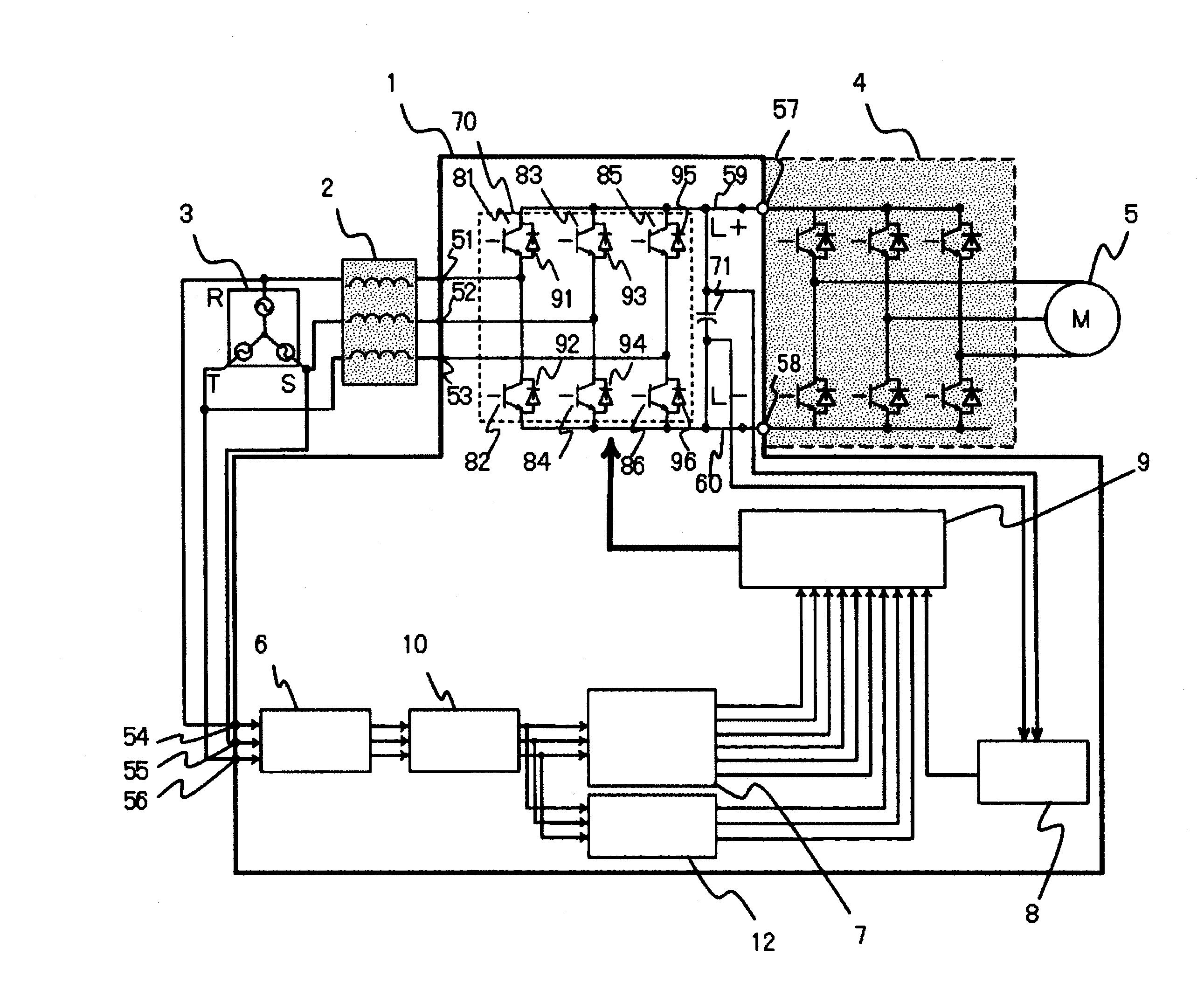
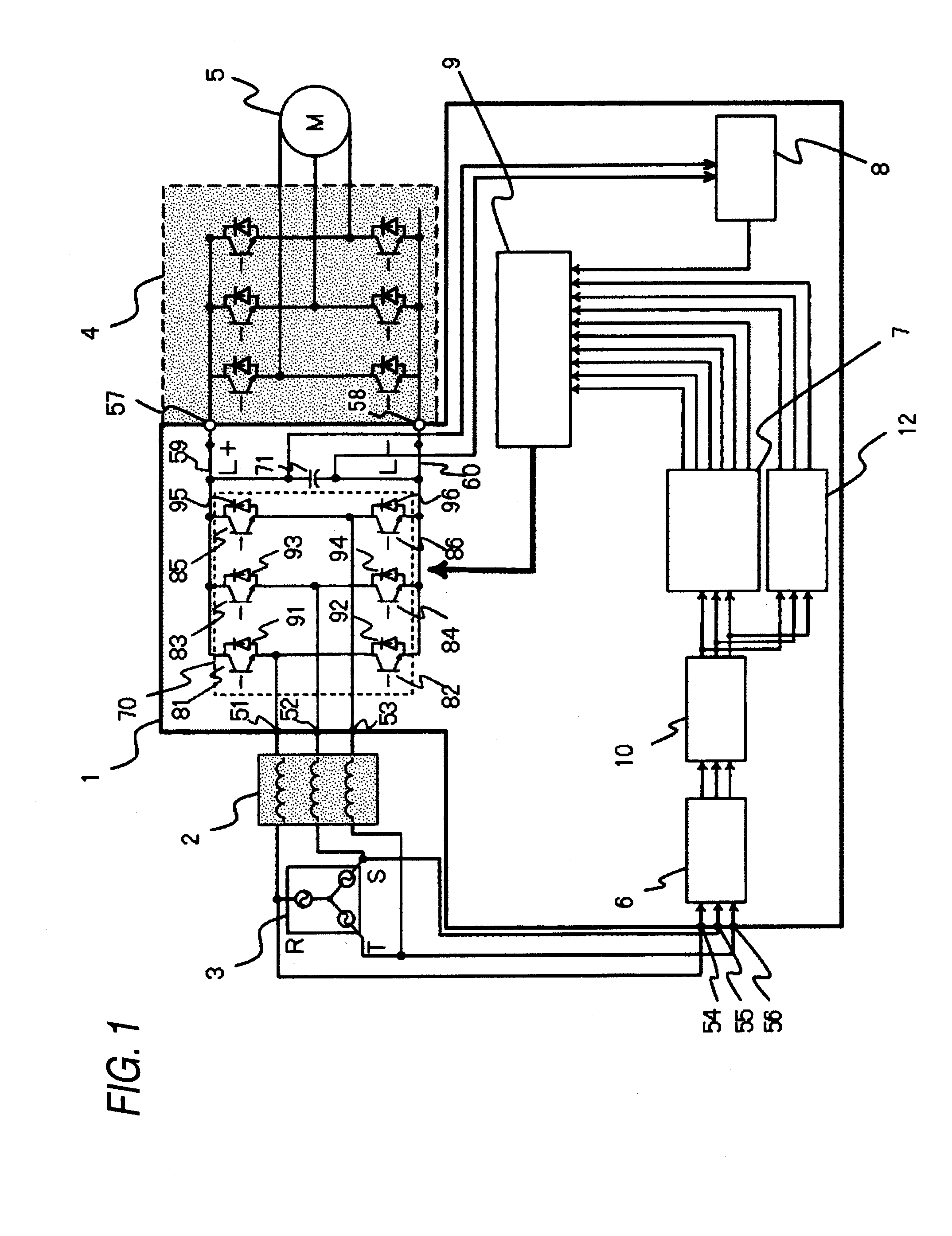
[0022]FIG. 1 is a block diagram showing a structure of a power regenerative converter according to the embodiment. The structure will be described below. A power regenerative converter 1 is disposed between a three-phase AC power supply 3 for generating AC powers having three phases (R, S and T phases) and an inverter device 4 for variable speed controlling a motor 5. The power regenerative converter 1 includes AC power terminals 51, 52, 53, 54, 55 and 56. The AC power terminals 51, 52 and 53 are connected to respective power terminals of the three-phase AC power supply 3 through a reactor 2, and the AC power terminals 54, 55 and 56 are connected to the respective power terminals of the three-phase AC power supply 3 without the reactor 2. Moreover, DC power terminals 57 and 58 of the power regenerative converter 1 are connected to DC buses in the inverter device 4. DC buses 59 and 60 connected to the DC power terminals 57 and 58 are disposed in the power regenerative converter 1, an...

second embodiment

[0056]Description will be given to an embodiment in which a function for extracting a distortion component of a three-phase AC power supply and obtaining a distortion frequency, a distortion amplitude and a distortion ratio of the distortion component is added to the first embodiment in order to grasp the distortion component in the case in which the distortion component is mixed into the three-phase AC power supply.

[0057]FIG. 8 is a block diagram showing a structure of a power regenerative converter according to the embodiment. FIG. 9 is a diagram showing an internal structure of a distortion component extracting portion. In a power regenerative converter 1A according to the embodiment shown in FIG. 8, a distortion component extracting portion 11 for extracting a distortion component to be mixed into a line voltage waveform of a three-phase AC power supply 3 is provided after the fundamental waveform generating portion 10 in the power regenerative converter 1 according to the first...

third embodiment

[0062]Description will be given to an embodiment in which a function for carrying out an ON / OFF control of a regenerative transistor depending on a state of a distortion component when the distortion component is mixed into a three-phase AC power supply is added to the first embodiment.

[0063]FIG. 10 is a block diagram showing a structure of a power regenerative converter according to the embodiment. FIG. 11 is a block diagram showing an internal structure of a base driving signal output portion 9A according to the embodiment. FIG. 12 is a time chart in a regenerating operation of a power regenerative converter 1B, showing a temporal change in a regenerative transistor and a regenerative current which correspond to a line voltage waveform and a fundamental waveform of a three-phase AC power supply 3 in which a distortion component is mixed.

[0064]In the power regenerative converter 1B according to the embodiment shown in FIG. 10, a distortion component extracting portion 11 for extrac...


PUM


Abstract

There are provided a smoothing capacitor (71) for storing an induced electromotive force generated by a three-phase induction motor (5), a regenerative transistor (81 to 86) for switching a terminal voltage of the smoothing capacitor to carry out a power regenerating operation over a three-phase AC power supply (3), a line voltage detecting portion (6) for detecting a line voltage of the three-phase AC power supply, a fundamental waveform generating portion (10) for generating, from a signal output from the line voltage detecting portion, a fundamental waveform defined to be a line voltage waveform of the three-phase AC power supply in which a source voltage distortion component is not mixed, a base driving signal creating portion (7) for creating a base driving signal to be used for an ON / OFF control of the regenerative transistor based on a signal output from the fundamental waveform generating portion, and a base driving signal output portion (9) for outputting the base driving signal.

Description

TECHNICAL FIELD[0001]The present invention relates to a power regenerative converter.BACKGROUND ART[0002]A power regenerative converter is disposed between an inverter device for variable speed controlling a three-phase induction motor and a three-phase AC power supply and a reactor is provided between the three-phase AC power supply and the power regenerative converter. The power regenerative converter regenerates, in a three-phase AC power supply, an induced electromotive force generated in a speed reduction of a three-phase induction motor (hereinafter referred to as a motor). When a speed of the motor is reduced, a current obtained by the induced electromotive force thus generated flows into both terminals of a smoothing capacitor in the power regenerative converter. When a regenerative transistor of the power regenerative converter is turned ON, a regenerative current flows from the smoothing capacitor into a power supply.[0003]Thus, a difference between a voltage of the smooth...

Claims


Application Information

Patent Timeline
Patent Type & Authority Applications(United States)
IPC IPC(8): H02P3/18
CPCH02M7/797H02P29/024H02P27/06H02P9/006H02P29/0241
Inventor HAYASHI, YOSHITOMOIWATA, AKIHIKO
Owner MITSUBISHI ELECTRIC CORP
Why Eureka
Try Eureka