
Control system for garage door

a control system and garage door technology, applied in the direction of program control, instruments, anti-theft devices, etc., can solve the problems of controller misjudgment of keys, change of charge time and discharge time, and garage door misinterpretation, so as to prolong the service life of the keyboard, improve the transmission of control signals, and increase the operation liability

Inactive Publication Date: 2010-03-04
POWELL INDUSTRY CO LTD
View PDF7 Cites 5 Cited by
  • Summary
  • Abstract
  • Description
  • Claims
  • Application Information

AI Technical Summary

Benefits of technology

[0006]To overcome the above drawbacks existing in the prior art, the present invention provides a control system and method for a garage door, which improves the control signal transmission from keyboard to the controller thereof to fulfill the objects of increasing the operation liability and extending the service life of the keyboard.
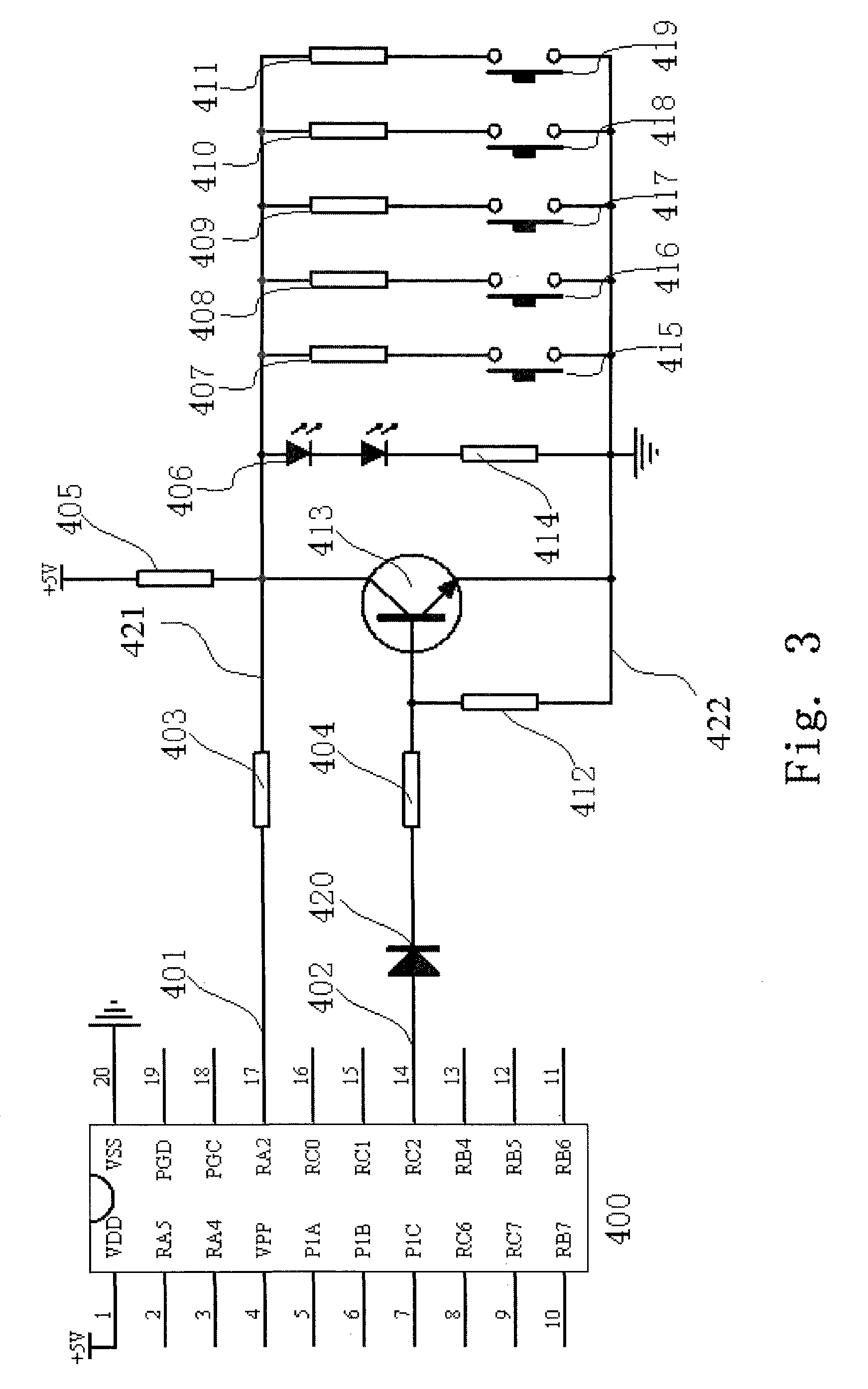
[0011]Therefore, when the keyboard is idle, each key is disconnected to cut every key mapping signal shunt, thereby the voltage output by the voltage signal output circuit is equal to the provided driving voltage; when a key is pressed, the key mapping signal shunt where the key locates is connected and forms a series circuit with the divider resistor. Because the resistors respectively connected with the keys in series are different, the voltage on the key mapping signal shunt is different when different key is pressed. The voltage on the key mapping signal shunt is transmitted to the controller via the voltage signal output circuit for the controller to determine the corresponding key by the voltage on the key mapping signal shunt, so as to take correct action to operate the garage door and a working light. The present invention adopts resistors of different values to distinguish different keys. As comparing to capacitors, resistors have more stable parameters, are less affected by factors such as environmental temperature and humidity, and therefore reduce misjudgment of keys; besides, resistors have longer service life, low cost and low failure rate; and the keyboard has simple circuit structure, and needs only two wires connected with the driving circuit of the keyboard of the controller, and therefore is convenient to connect, simple and reliable.
[0022]The wall keyboard with the improvement by present invention has the advantages of stable operation, less misaction, lower cost, extended service life, convenient use and safety.

Problems solved by technology

The change of capacitor value causes the change of charge time and discharge time, and therefore causes the controller to misjudge the keys and the garage door to misact.
In addition, capacitors have limited service life, and the price thereof is higher than resistors.

Method used


Image

  • Control system for garage door
  • Control system for garage door
  • Control system for garage door

Examples


Embodiment Construction

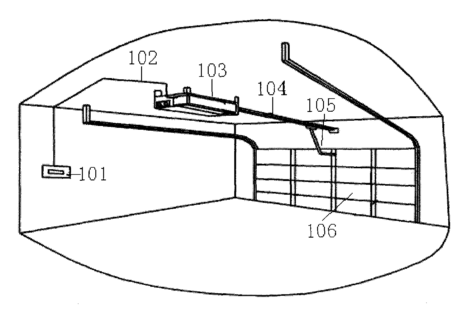
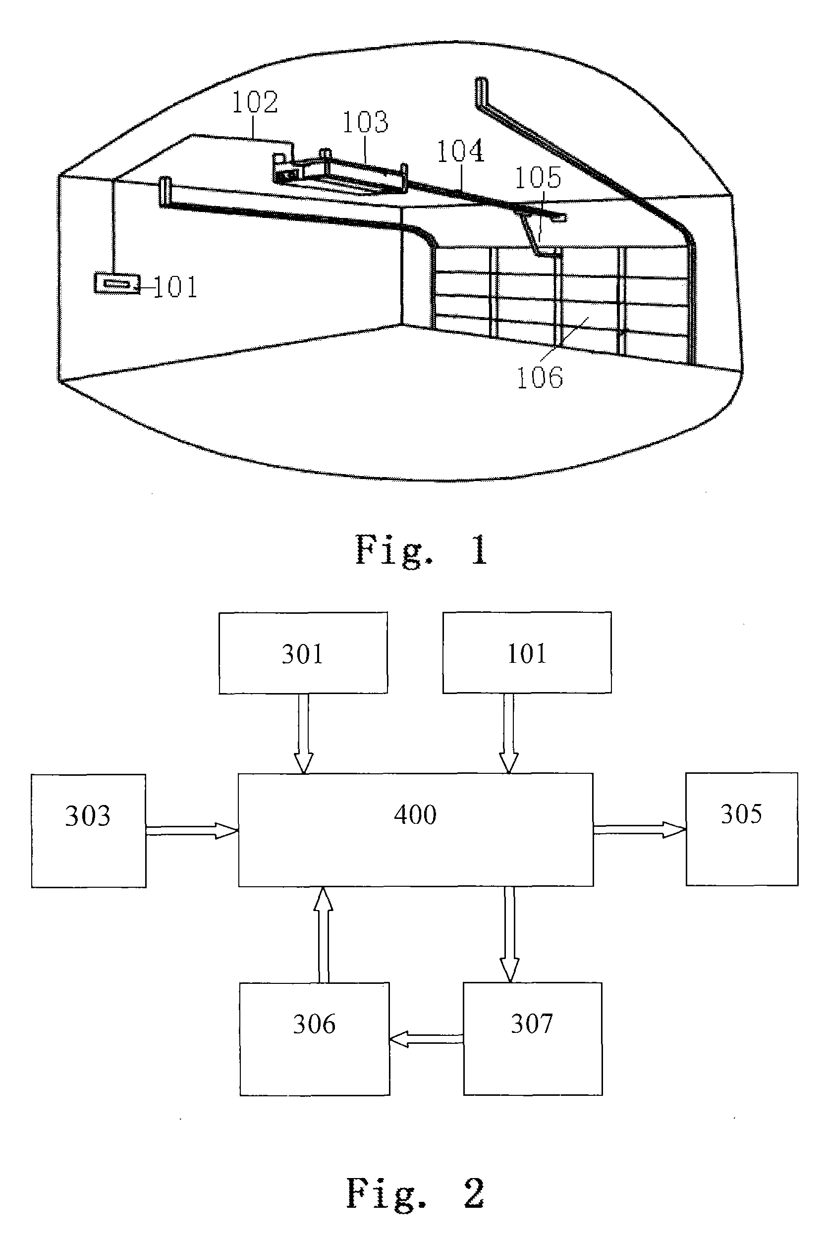
[0027]Referring to FIG. 1 of the drawings, a control system for a garage door according to a preferred embodiment of the present invention is illustrated, wherein a keyboard 101 provided on a wall is connected to a head 103 comprising a motor, a controller, a motion detecting device and so on therein via a wire 102. A user controls the motor in the head 103 to rotate positively or reversely via the keyboard 101, wherein the motor in the head 103 pushes or pulls a garage door 106 via a transmission chain 104 and a connected rod 105, so as to open or close the garage door 106.

[0028]Referring to FIG. 2 of the drawings, the control system may further comprise an infrared alarm means 301, a remote controller 303, an indicating lamp 305 and the motion detecting device 306, all of which are connected with a single chip 400 which acts as a core of the controller. A power and transmission device 307 illustrated in the drawings comprises the motor and a transmission mechanism.

[0029]An electri...


PUM


Abstract

A control system for garage door includes a motor, a controller controlling operation of the motor, and a keyboard for inputting an instruction into the controller. The keyboard includes a plurality of keys, a plurality of resistors, a divider resistor for sharing voltage, and a voltage signal output circuit. The resistors correspond to the keys. Each key is connected with one of the resistors in series to form a key mapping signal shunt. The key mapping signal shunts are connected in parallel to form a group of key mapping signal shunts. The divider resistor is connected with the group of key mapping signal shunts in series to form a series circuit. A driving voltage is applied on the series circuit. The voltage signal output circuit is for transmitting a voltage on the group of key mapping signal shunts to the controller.

Description

BACKGROUND OF THE PRESENT INVENTION[0001]1. Field of Invention[0002]The present invention relates to a control system for garage door, and more particularly to a control system comprising a wall keyboard which outputs different potentials to represent outputting different instructions by operating different keys.[0003]2. Description of Related Arts[0004]In a garage door operator system, the user inputs instructions via an operation keyboard provided on a wall, wherein the electric circuit of the keyboard transfers states of the keys into electric signals of different values and then sends to a controller via one or more wires, and at last the controller controls a motor or other actuators to open or close the garage door, and turn on or turn off the working light.[0005]The door operator ordinarily adopts the reactance method to transfer states of the keys into electric signals of different values, wherein the wall keyboard of the garage door operator is connected with the controller...

Claims


Application Information

Patent Timeline
Patent Type & Authority Applications(United States)
IPC IPC(8): G08B29/00
CPCE05Y2400/80E05Y2900/106G07C9/00182E05F15/40G07C2009/00928E05F15/00G07C2009/00793
Inventor WANG, JIANHUALUO, ZIJIAN
Owner POWELL INDUSTRY CO LTD
Learn More