Scanning system for lidar

a lidar and scanning system technology, applied in the field of scanning systems, can solve the problems of image distortion, conventional nodding mirror system, and inability to accurately detect the position of the polygonal mirror,

Inactive Publication Date: 2010-03-04
AUTONOSYS
View PDF6 Cites 158 Cited by
  • Summary
  • Abstract
  • Description
  • Claims
  • Application Information

AI Technical Summary

Benefits of technology

[0015]Accordingly, the present invention relates to a scanning system for lidar comprising: a nodding mirror having a nodding axis and a centered position; a rotary electromagnetic drive configured to rotate the nodding mirror clockwise and counterclockwise about the nodding axis, comprising: a yoke including a permanent magnet, and an arm including a coil at one end of the arm, wherein the coil is enclosed within the yoke, and an opposite end of the arm is coupled to the nodding mirror, such that movement of the coil within the yoke in response to a current causes the nodding mirror to rotate; a rotary optical encoder configured to produce an output signal in response to rotation of the nodding mirror; and control circuitry configured to adjust the current provided to the rotary electromagnetic drive in response to the output signal of the rotary optical encoder, such that the nodding mirror rotates in a reference scan pattern.

Problems solved by technology

In contrast, the collection efficiency is not uniform over all angular positions of the polygonal mirror.
Furthermore, owing to manufacturing errors, the dimensions of the polygonal mirror may deviate from those of a regular polygon, leading to image distortion.
Nodding-mirror systems with a variety of configurations have been implemented in scanning systems for lidar, but these conventional nodding-mirror system have some important limitations.
However, these nodding-mirror systems have the disadvantage that the gear mechanism of the stepper motors introduces backlash, limiting the accuracy and the angular speed of the rotation of the nodding mirror.
However, these nodding-mirror systems have the disadvantage that the galvanometer motors provide relatively low torque, limiting the size of the nodding mirror that can be rotated.
The effectiveness of the closed-loop feedback control is limited by the accuracy and resolution of the detectors.

Method used


Image

  • Scanning system for lidar
  • Scanning system for lidar
  • Scanning system for lidar

Examples


Embodiment Construction

Scanning System for Lidar Including an Optimized Nodding-Mirror System

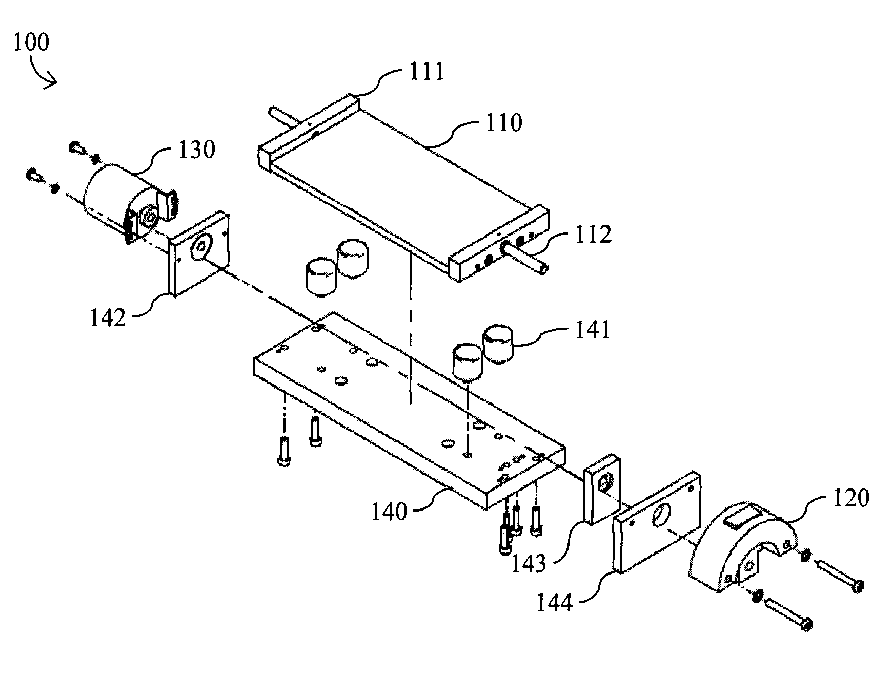
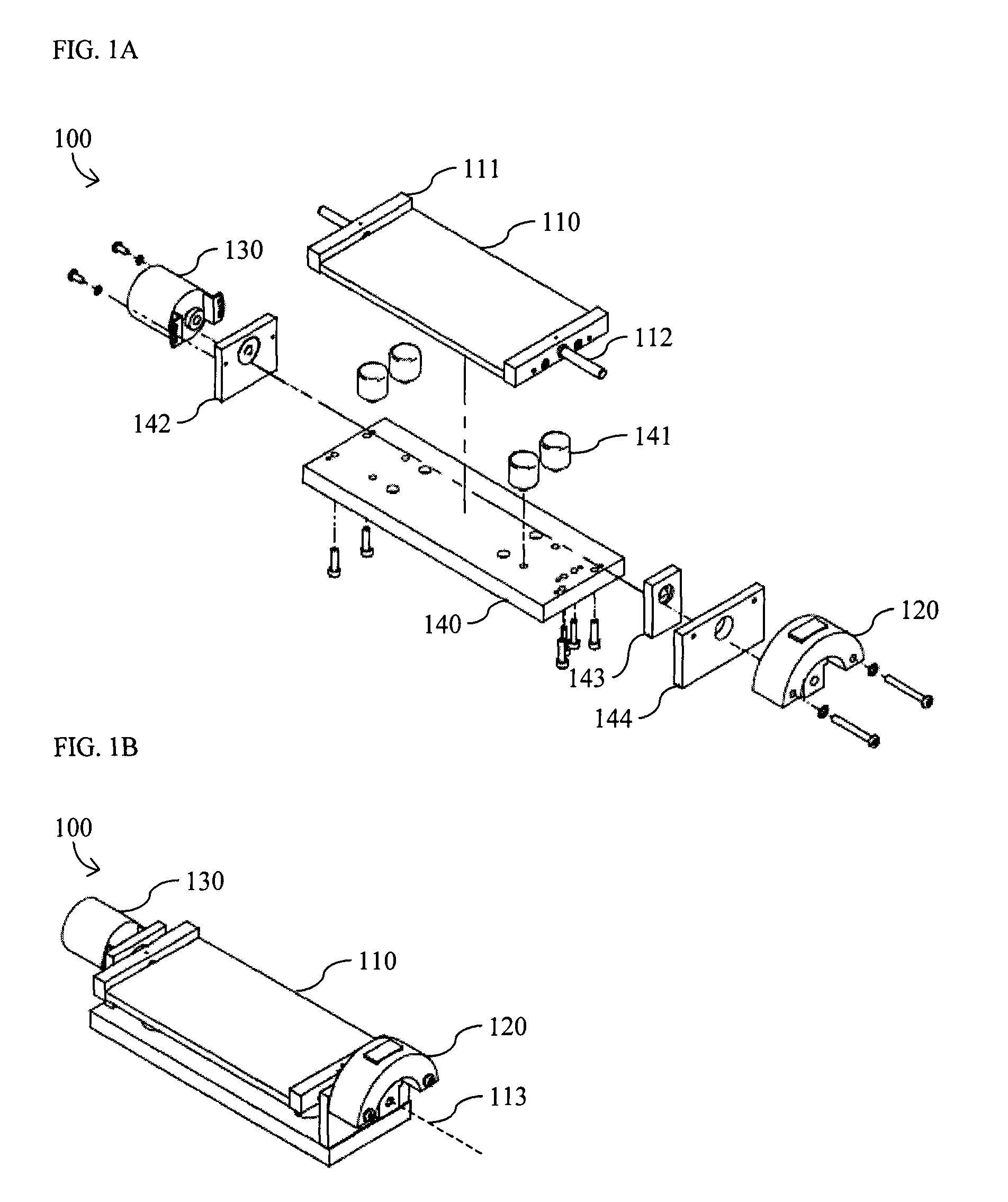
[0030]With reference to FIGS. 1A and 1B, the present invention provides a scanning system for lidar including an optimized nodding-mirror system 100. The nodding-mirror system 100 includes a nodding mirror 110, a rotary electromagnetic drive 120, a rotary optical encoder 130, and control circuitry (not shown). The nodding mirror 110 has a nodding axis 113 and a centered position. In the illustrated embodiment, the nodding mirror 110, which is approximately 200 mm long and 60 mm wide, is mounted on a mirror support 111 that includes a shaft 112, which coincides with the nodding axis 113 about which the nodding mirror 110 rotates. Preferably, the nodding mirror 110 is planar.

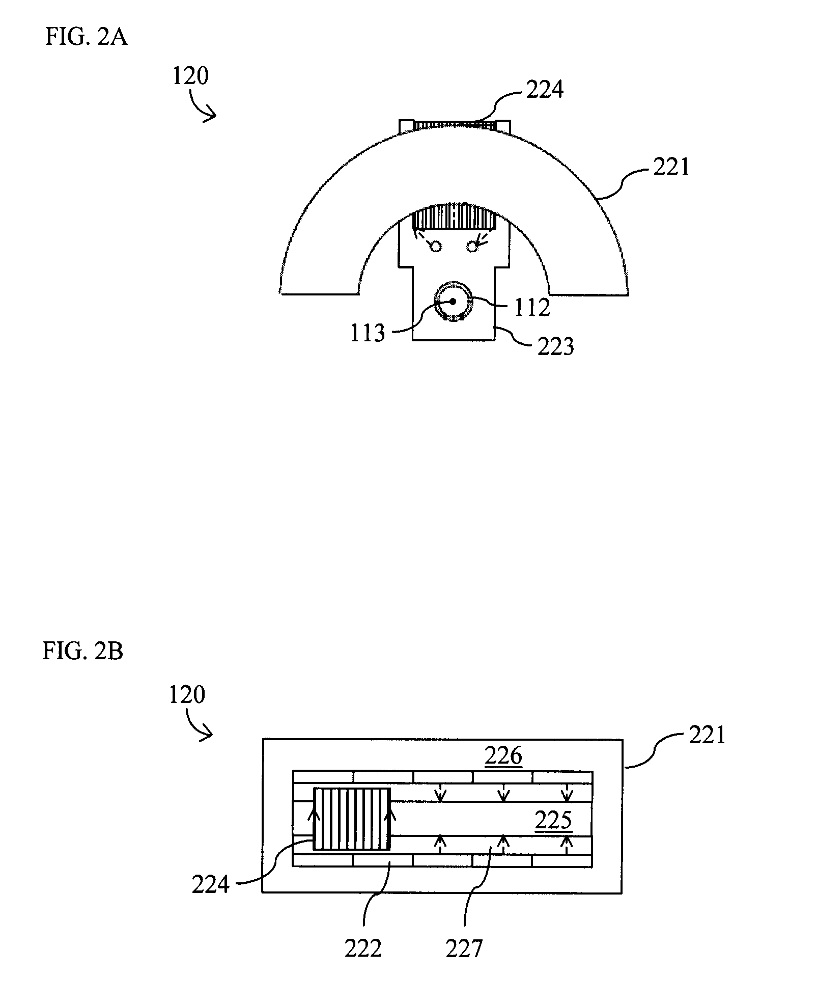
[0031]The nodding mirror 110 is coupled to both the rotary electromagnetic drive 120 and the rotary optical encoder 130 via the shaft 112. Preferably, the rotary electromagnetic drive 120 is coupled to the shaft 112 at one end of the nodding mir...


PUM


Abstract

The present invention relates to a scanning system optimized for lidar that includes a nodding mirror, a rotary electromagnetic drive, a rotary optical encoder, and control circuitry. The rotary electromagnetic drive includes a yoke incorporating a permanent magnet, and an arm having a coil at one end of the arm. The coil is enclosed within the yoke, and an opposite end of the arm is coupled to the nodding mirror, such that movement of the coil within the yoke in response to a current causes the nodding mirror to rotate. The rotary optical encoder produces an output signal in response to rotation of the nodding mirror, which serves as feedback to the control circuitry. The control circuitry adjusts the current provided to the rotary electromagnetic drive in response to the output signal, such that the nodding mirror rotates in a reference scan pattern.

Description

CROSS-REFERENCE TO RELATED APPLICATIONS[0001]The present invention claims priority from U.S. Patent Application No. 60 / 855,146 filed Oct. 30, 2006, which is incorporated herein by reference.TECHNICAL FIELD[0002]The present invention relates to scanning systems and, in particular, to scanning systems for lidar.BACKGROUND OF THE INVENTION[0003]Light detection and ranging (lidar) is a technique for remote imaging, in which the distance of an object is measured using laser light. A typical lidar system includes a rangefinder and a scanning system. The rangefinder, typically, includes a laser with a wavelength in the ultraviolet (UV) to near-infrared (NIR) range, as well as a receiver. The distance to an object can be determined by measuring the time taken for outgoing pulses of laser light to be reflected back into the receiver, or by measuring the phase shift between an outgoing and an incoming modulated beam of laser light. The scanning system, typically, includes a mirror system for ...

Claims


Application Information

Patent Timeline
Patent Type & Authority Applications(United States)
IPC IPC(8): G02B26/12G02B26/10
CPCG02B26/105G01S7/4817G01S7/4972
Inventor O'NEILL, JAMESMOORE, WILLIAM T.WILLIAMS, KEVINBRUCE, ROBERT
Owner AUTONOSYS
Why Eureka
Try Eureka