Light reflecting plate and method of manufacturing the same, and light reflecting device

a technology of light reflecting plate and manufacturing method, which is applied in the direction of lighting and heating apparatus, instruments, and using daylight, can solve the problems of uneven illumination, glare increase, and light intensity generally attenuation by several tens of percent, and achieve excellent reflection efficiency, reduce light reflectance, and reduce the effect of glar

Inactive Publication Date: 2010-03-04
TOYO KOHAN CO LTD
View PDF2 Cites 27 Cited by
  • Summary
  • Abstract
  • Description
  • Claims
  • Application Information

AI Technical Summary

Benefits of technology

[0028]As described above, according to the light reflecting plate of the present invention, because it is equipped with the light reflecting layer made up of the film of silver or silver alloy, or the film of aluminum or aluminum alloy, it has excellent reflection efficiency particularly over the entire visible light region.
[0029]Since arithmetic average roughness (Ra) on the surface of the light reflecting layer is as small as 0.10 to 0.30 μm, high light reflectance by regular reflection can be maintained. In addition, since arithmetic average waviness (Wa) is imparted on the surface of the same light reflecting layer and the range of arithmetic average waviness (Wa) is set to 0.3 to 2.5 μm, diffuse reflection of light can be generated without reducing light reflectance by regular reflection.
[0030]Thus, glare of reflected light can be reduced while maintaining high light reflectance by regular reflection.
[0031]According to the method of manufacturing a light reflecting plate of the present invention, a light reflecting layer made of a silver film

Problems solved by technology

Sho58-93101, spread of light ray flux of sunlight to be taken in is substantially limited to the size of a daylighting section 1 as illustrated in FIG. 9, and the light ray flux is reflected and transmitted by the mirror-finished inner wall of a light ray guiding tube 2 while maintaining the spread when the light was taken in, so that light reflected and transmitted through the light ray guiding tube 2 is outputted from the light emitting section intensively to one or a plurality of areas, and there is a problem that uneven illumination occurs.
Now, there is a problem that

Method used


Image

  • Light reflecting plate and method of manufacturing the same, and light reflecting device
  • Light reflecting plate and method of manufacturing the same, and light reflecting device
  • Light reflecting plate and method of manufacturing the same, and light reflecting device

Examples


first embodiment

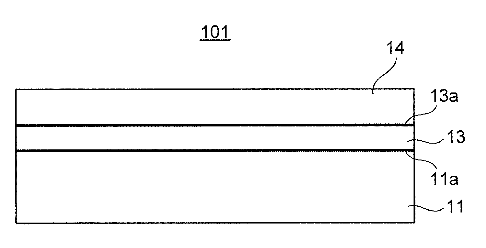
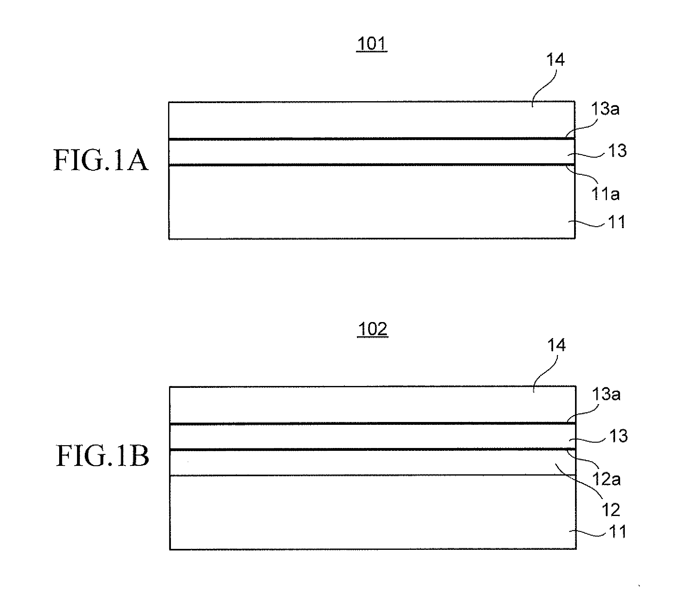
(2) Description of light reflecting plate

[0045](i) Structure of light reflecting plate[0046](a) Structure of substrate[0047](b) Structure of light reflecting layer[0048](c) Structure of protective film

[0049](ii) Another structure of light reflecting plate

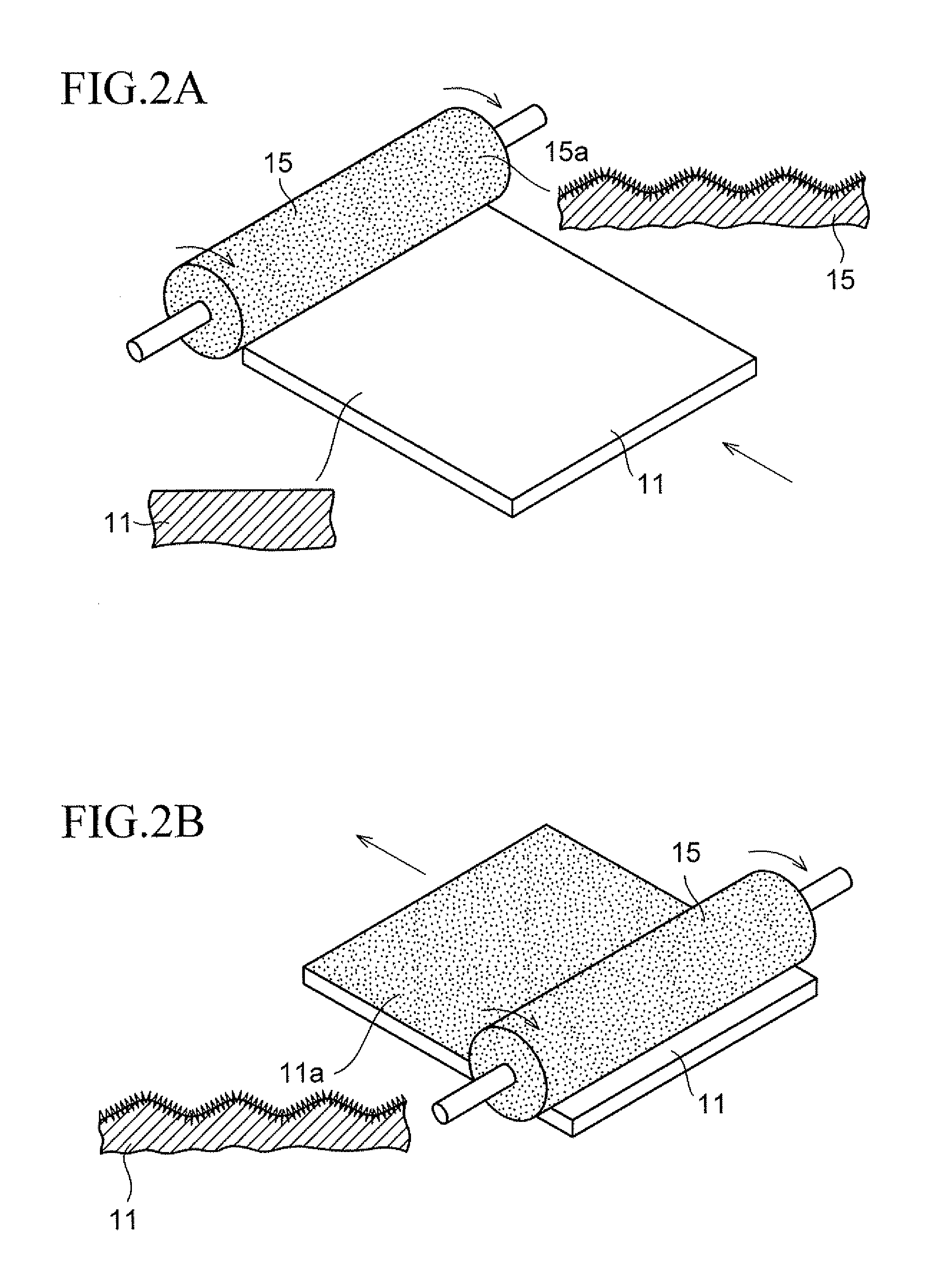
[0050](iii) Surface texture of light reflecting layer of light reflecting plate and its imparting method

[0051](iv) Method of manufacturing light reflecting plate

[0052](v) Evaluation of surface texture

second embodiment

(3) Description of light reflecting device according to the present invention

[0053](i) Mirror duct

DESCRIPTION OF EMBODIMENTS

(1) Description of Progress of the Present Invention

[0054]FIGS. 6A, 6B, and 60 are schematic views explaining the relationship between the surface texture of reflecting surface and the reflection characteristics of light.

[0055]FIG. 6A illustrates the reflection characteristics of light in the case where reflecting surface 20a does not have waviness and the arithmetic average roughness (Ra) is small. Reference numeral 21 indicates incident light, and 22a indicates reflected light. In this case, since regular reflection becomes strong on the reflecting surface 20a (regular reflectance becomes higher), the reflected light 22a is felt glaring. On the other hand, as illustrated in FIG. 6B, since diffuse reflection becomes stronger on reflecting surface 20b (diffuse reflectance becomes higher) when the arithmetic average roughness (Ra) of the reflecting surface 20b b...

example 1 (

A1)

[0130]On cold-rolled steel sheet (the substrate 11, the same applies below) to which surface texture with the arithmetic average roughness (Ra) of 0.1 μm and the arithmetic average waviness (Wa) of 0.3 μm was imparted, silver (Ag) film (the light reflecting layer 13, the same applies below) having the thickness of 100 nm was formed by electroless plating method using ammoniacal silver nitrate aqueous solution of approximately pH 10 and reducer (hydrazine sulfate) aqueous solution of approximately pH 10.

[0131]Note that the arithmetic average roughness (Ra) and the arithmetic average waviness (Wa) were measured based on items of (Characteristics Evaluation) below. The same applies below. Note that the cold-rolled steel sheet of the substrate 11 was simply described as steel sheet on the table of FIG. 3. The same applies below.


PUM

PropertyMeasurementUnit
Lengthaaaaaaaaaa
Lengthaaaaaaaaaa
Fractionaaaaaaaaaa

Abstract

Provided is a light reflecting plate capable of reducing glare of reflected light while maintaining high light reflectance by regular reflection. The light reflecting plate includes a base, a light reflecting layer that is formed on the base and made of silver or silver alloy, or aluminum or aluminum alloy, in which arithmetic average roughness (Ra) is 0.10 to 0.30 μm and arithmetic average waviness (Wa) is 0.30 to 2.50 μm on a surface of the light reflecting layer.

Description

CROSS-REFERENCE TO RELATED APPLICATIONS[0001]This application is a continuation of prior International Patent Application No. PCT / JP2008 / 60516, filed Jun. 9, 2008, the entire contents of which are incorporated herein by reference.BACKGROUND OF THE INVENTION[0002]1. Field of the Invention[0003]The present invention relates to a light reflecting plate, a method of manufacturing the same, and a light reflecting device using the light reflecting plate, more particularly to a light reflecting plate with excellent light reflection characteristics, a method of manufacturing the same, and a light reflecting device such as a mirror duct that illuminates the interior of a room by guiding sunlight indoors by the light reflecting plate.[0004]2. Description of the Related Art[0005]Conventionally, as a light reflecting device equipped with a light reflecting plate, a mirror duct that guides sunlight indoors to use it as illumination is known (Japanese Patent Laid-open No. Sho58-93101, Japanese Pa...

Claims


Application Information

Patent Timeline
IPC IPC(8): G02B5/08C25D7/08B05D5/06
CPCF21S11/00F21V7/22G02B5/0215G02B5/0284G02B5/0231G02B5/0268G02B5/0221F21V7/28F21V7/24
Inventor NISHI, MARIOHBA, MITSUYOSHIOHSHIMA, TATSUYA
Owner TOYO KOHAN CO LTD
Why Eureka
Try Eureka