Method and apparatus for creating soil or rock subsurface support

a subsurface support and rock technology, applied in earth drilling, mining structures, construction, etc., can solve the problems of reducing the ability of the support to provide designed support, requiring active support, and unstable earth surrounding or near a man made structure, etc., to achieve cost-effective, high-resistance corrosion resistance, and simple shortened body length

Inactive Publication Date: 2010-03-04
BARRETT ROBERT K +2
View PDF99 Cites 6 Cited by
  • Summary
  • Abstract
  • Description
  • Claims
  • Application Information

AI Technical Summary

Benefits of technology

[0011]In another embodiment of the present invention, the support device is in the form of an improved soil nail including a fiberglass body and a metal tip. The metal tip is preferably made from a single piece of metal, such as a machined ingot of hardened steel. The tip comprises a contacting portion or stinger that makes contact with the ground when emplaced, and a proximal base portion that is received within an opening in the distal end of the fiberglass body thus allowing the tip to be attached to the fiberglass body. The base portion may be attached by a compression fit within the opening of the body and / or may be secured by an appropriate bonding agent, such urethane glue. The size and dimensions of the soil nail can be modified for the intended purpose of use. One common size acceptable for use in many soil stabilization efforts includes a fiberglass body of twenty feet in length and a contacting portion of the metal tip extending approximately six inches in length from the distal end of the fiberglass body. For those applications in which a shorter body is required, the same tip construction can be used, and the length of the body can simply be shortened. Unlike most prior art soil nails, the soil nail of the present invention has a tubular shaped body without projections which allows the soil nail to be emplaced by the soil nail launcher disclosed in the U.S. Pat. No. 5,044,831. The use of a soil nail with a fiberglass body in conjunction with a metal tip provides many advantages. The fiberglass body provides a more cost effective solution than traditional soil nails that are just made of metal. The fiberglass body also is highly resistant to corrosion, even more so than many metal soil nails within corrosion treated surfaces. The weight of the soil nail of the present invention is also less than a metal soil nail, allowing it to achieve greater velocity when emplaced by a soil nail launcher, thus enhancing its ability to penetrate the ground. The strength of the soil nail is not compromised because the fiberglass has adequate strength, and has a greater elastic limit as compared to many metal soil nails enabling the nail to handle even greater tensile and shear loads. Although the soil nail has a relatively smooth outer surface allowing it to be emplaced by a launcher, the surface characteristics of the fiberglass provide excellent adhesion with soil. Additionally, the stinger can be especially designed to handle particular soil or rock formations without having to modify the body of the soil nail. For example, in more dense soil or rock formations, the stinger shape can be modified prior to assembly with the body thus making the soil nail more adaptable for many uses.

Problems solved by technology

One particular problem associated with subsurface supports which may be made of iron, steel, or other metals is that over time, corrosion takes place which ultimately degrades the ability of the support to provide designed support for an overlying structure.
In some cases, the earth surrounding or near a man made structure becomes unstable and requires active support, such as by a tieback.

Method used


Image

  • Method and apparatus for creating soil or rock subsurface support
  • Method and apparatus for creating soil or rock subsurface support
  • Method and apparatus for creating soil or rock subsurface support

Examples


Embodiment Construction

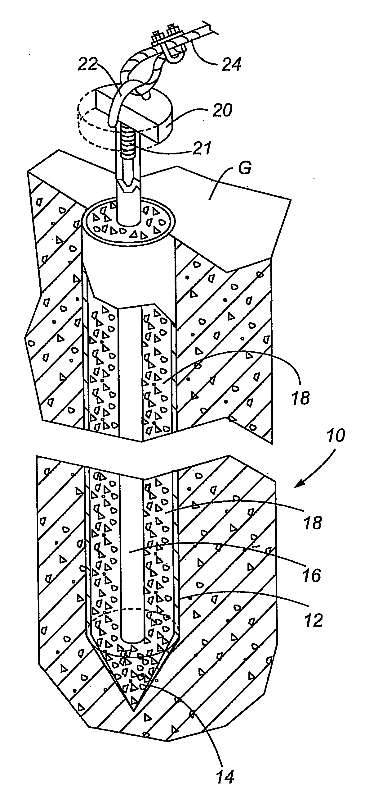
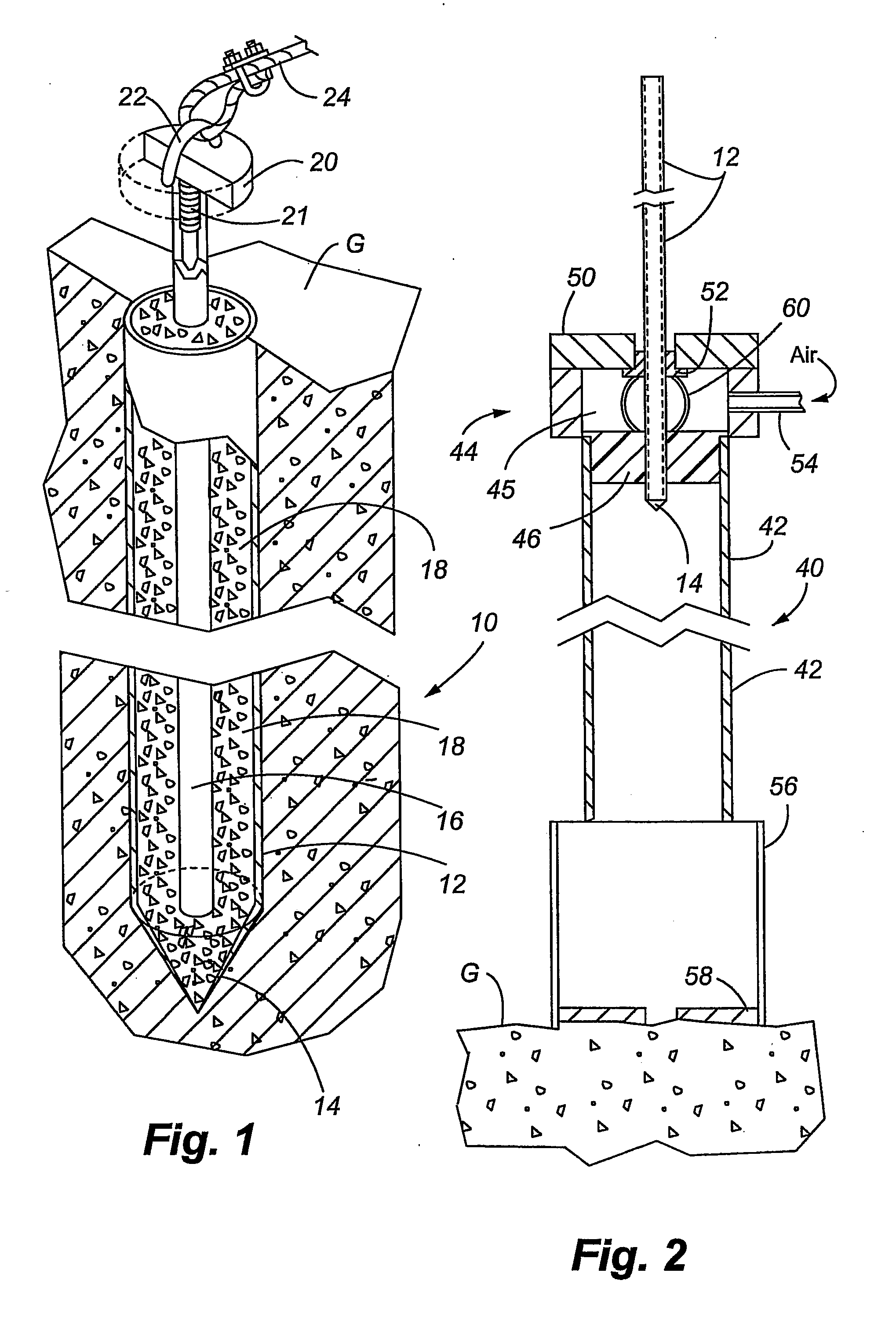
[0028]Referring to FIG. 1, the subsurface support 10 in a first embodiment of the present invention is shown installed in the ground G. The support device includes an outer member, preferably in the form of a steel or iron tube 12 having a selected length and diameter, and having an integral pointed tip 14. The tip 14 can be conical in shape that facilitates emplacement of the outer tube as by a launcher, as discussed below. After the outer tube is emplaced, the stabilizing mixture is placed in the interior chamber of the outer tube. Then, an inner support member that can be in the form of an epoxy coated steel rod or bar is then placed within the stabilizing mixture prior to hardening of the mixture. When the stabilizing mixture cures, the inner support member 16 can provide support to an overlying structure in compression, tension, and / or shear. Depending upon the design requirements of the particular structure to be built, a plurality of subsurface supports may be emplaced at des...


PUM


Abstract

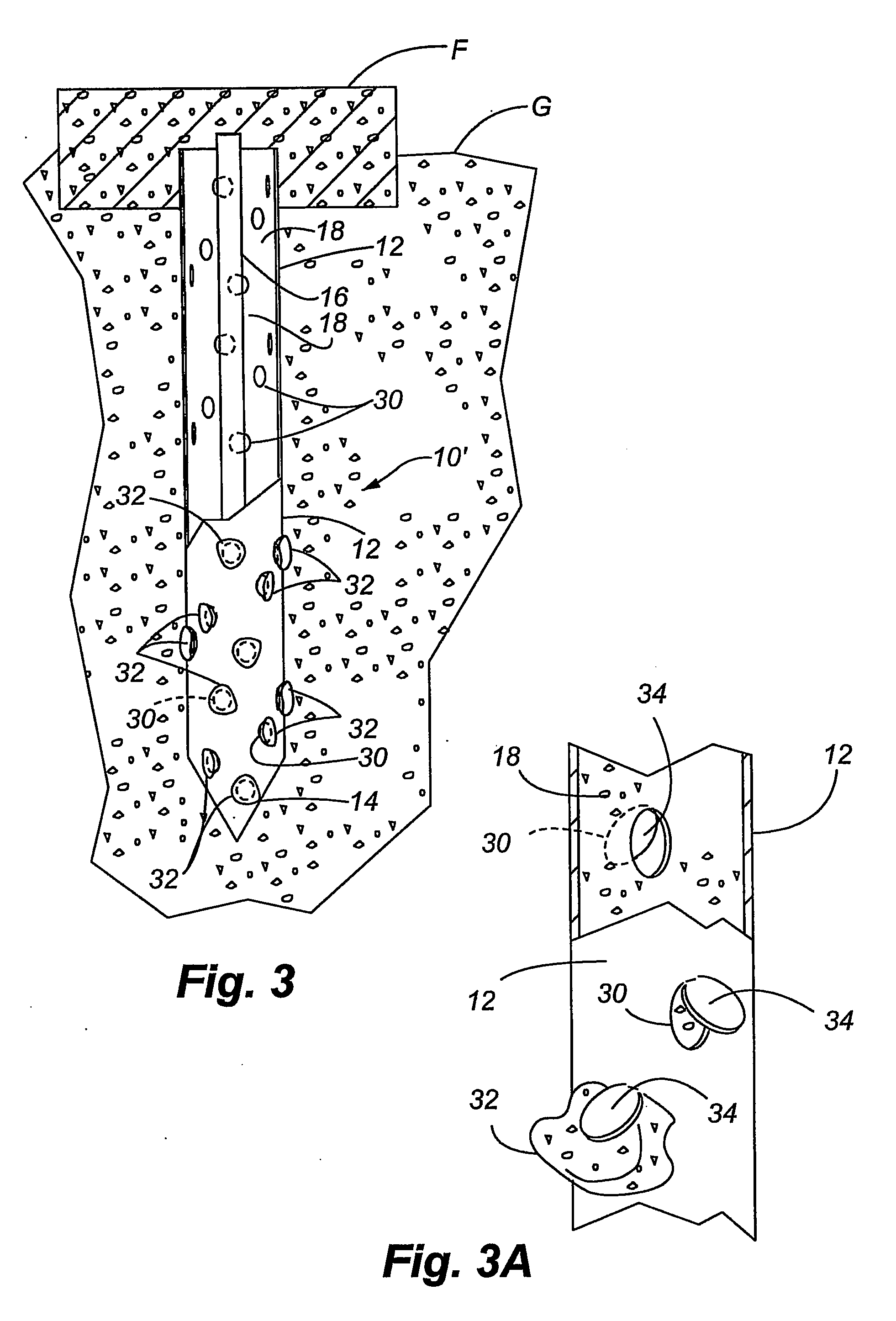
A subsurface support is provided in the form of a soil nail. The soil nail has asperities formed on the outer surface thereof to improve the pullout capacity of the soil nail. The asperities can take a number of forms to include indentations, deformations and threads formed on the outer surface of the soil nail. Optionally, a stinger may be attached to a distal end of the soil nail to further enhance the pullout capacity of the soil nail.

Description

CROSS REFERENCE TO RELATED APPLICATIONS[0001]This application is a continuation-in-part application of co-pending U.S. application Ser. No. 11 / 460,317, filed on Jul. 27, 2006, entitled “METHOD AND APPARATUS FOR CREATING SOIL OR ROCK SUBSURFACE SUPPORT”, which is a continuation-in-part of copending U.S. application Ser. No. 10 / 741,951, filed on Dec. 18, 2003, entitled “METHOD AND APPARATUS FOR CREATING SOIL OR ROCK SUBSURFACE SUPPORT”, the disclosures of these applications being hereby incorporated by reference herein in their entirety.TECHNICAL FIELD[0002]The present invention relates generally to subsurface supports placed in the ground, and more particularly, to a method and apparatus for creating a soil or rock subsurface support that can be used in multiple ways to include support for excavations as a passive soil nail in tension, bending and / or shear, support to stabilize sloping terrain as a tieback in tension, support for an above ground structure as a micropile in compressio...

Claims


Application Information

Patent Timeline
Patent Type & Authority Applications(United States)
IPC IPC(8): E21D21/00
CPCE02D3/12E02D5/808E02D5/80
Inventor BARRETT, ROBERT K.RUCKMAN, ALBERT C.BARRETT, COLBY
Owner BARRETT ROBERT K
Why Eureka
Try Eureka