Blade and a method for making a blade

a blade and blade technology, applied in the field of blades, can solve the problems of increasing maintenance and replacement costs, shortening affecting the service life of the blade,

Active Publication Date: 2010-03-04
ROLLS ROYCE PLC
View PDF42 Cites 15 Cited by
  • Summary
  • Abstract
  • Description
  • Claims
  • Application Information

AI Technical Summary

Problems solved by technology

A disadvantage of such an approach is that the blade and in particular a composite blade will include a moisture path in the line of weakness which may then precipitate cracking through freeze-thaw cycles.
It will be understood that premature cracking will result in a shorter operational life for the blade and therefore increase costs for maintenance as well as replacement.
Further problems with respect to lines of we...

Method used


Image

  • Blade and a method for making a blade
  • Blade and a method for making a blade
  • Blade and a method for making a blade

Examples


Embodiment Construction

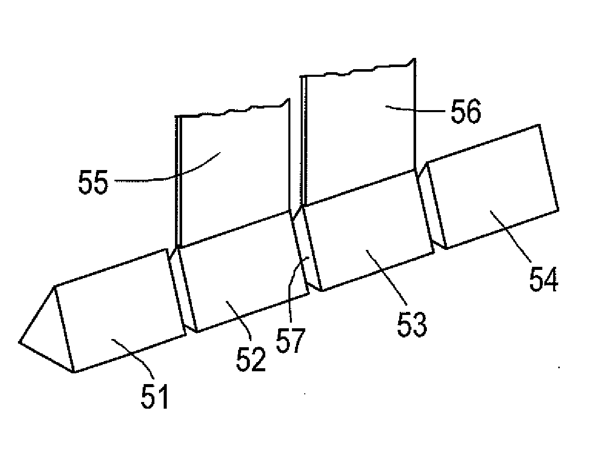
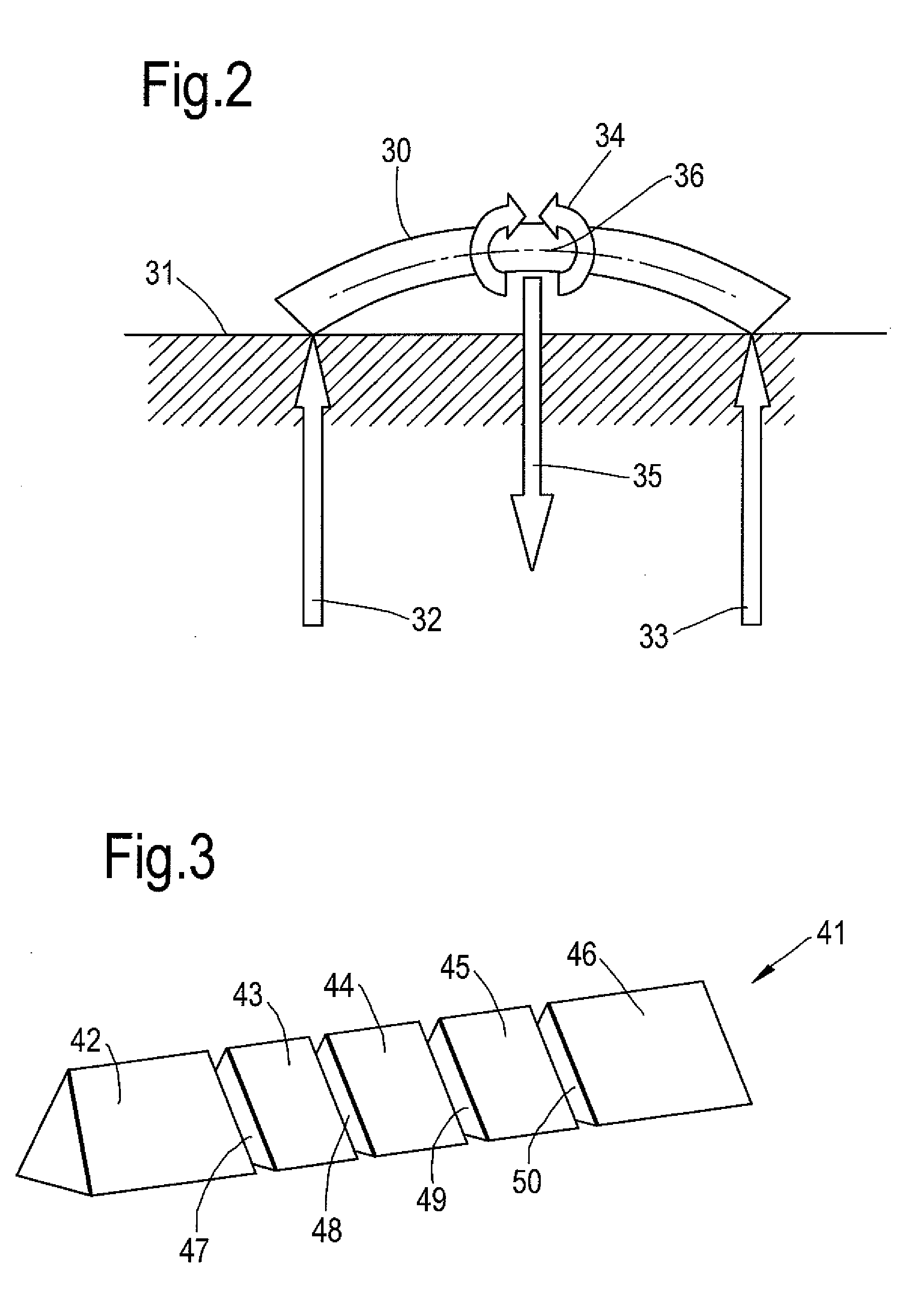
[0023]In accordance with the invention a root section for a blade for utilisation in gas turbine engines is constructed and manufactured to incorporate one or more shear layers. These shear layers are provided generally within a core defining a wedge in the root. Generally, the shear layers are located between neighbouring material in order to define parts which are frangible with respect to each other. Typically the layers are created through a plurality or set of segments associated together with a disjoint or slip layer between them. This disjoint or slip layer can be created through provision of a layer of non-adhesive solid, liquid or gel such as a silicon paste. In such circumstances the disjoint or slip layer is non-adhesive to the respective parts defining the core or side by side segments. An alternative would be to provide a layer of lower strength material which either crumbles, shatters or shears when subject to tension. An example of such a lower strength material may b...


PUM

PropertyMeasurementUnit
Weightaaaaaaaaaa
Adhesivityaaaaaaaaaa
Surfaceaaaaaaaaaa

Abstract

International regulations for aerofoils within gas turbine engines require the safe containment of a released aerofoil. The blade fragments must be contained within an engine casing. Smaller fragments will generally be easier to contain within the casing and therefore reduce the weight of that casing. However introducing lines of weakness may result in cavities and holes which are subject to moisture ingress and problems associated therewith. By providing a root section which incorporates a core having shear surfaces, blades can be designed which in normal use are subject to compressive loads and remain operational, but when subject to impact loads or bending forces create tension forces which cause fragmentation along the shear surfaces after initial energy losses by slippage. By providing the shear surfaces in cores their location is encapsulated avoiding problems with moisture ingress.

Description

CROSS REFERENCE TO RELATED APPLICATION[0001]This application is entitled to the benefit of British Patent Application No. GB 0815482.5, filed on Aug. 27, 2008.FIELD OF THE INVENTION[0002]The present invention relates to blades and more particularly to blades produced for gas turbine engines.BACKGROUND OF THE INVENTION[0003]Referring to FIG. 1, a gas turbine engine is generally indicated at 10 and comprises, in axial flow series, an air intake 11, a propulsive fan 12, an intermediate pressure compressor 13, a high pressure compressor 14, a combustor 15, a turbine arrangement comprising a high pressure turbine 16, an intermediate pressure turbine 17 and a low pressure turbine 18, and an exhaust nozzle 19.[0004]The gas turbine engine 10 operates in a conventional manner so that air entering the intake 11 is accelerated by the fan 12 which produce two air flows: a first air flow into the intermediate pressure compressor 13 and a second air flow which provides propulsive thrust. The inte...

Claims


Application Information

Patent Timeline
IPC IPC(8): F01D5/14B23P15/04
CPCF01D21/045F01D5/282Y10T29/49337F01D5/147Y02T50/672Y02T50/60
Inventor BECKFORD, PETER ROWLANDREAD, SIMONCARE, IAN COLIN DEUCHAR
Owner ROLLS ROYCE PLC
Why Eureka
Try Eureka