
Dispensing patterns including lines and dots at high speeds

a technology of dots and patterns, applied in the field of materials dispensing, can solve the problems of material waste, surface flatness, contact with the substrate, etc., and achieve the effect of reducing wall thickness

Pending Publication Date: 2010-03-04
SCIPERIO
View PDF43 Cites 15 Cited by
  • Summary
  • Abstract
  • Description
  • Claims
  • Application Information

AI Technical Summary

Benefits of technology

[0009]It is a further object, feature, or advantage of the present invention to provide a method and system for dispensing liquid materials, including viscous materials which allows for precise placement above the surface and including conformal surfaces.
[0010]Another object, feature, or advantage of the present invention is to increase the travel velocity associated with dispensing.
[0012]A still further object, feature, or advantage of the present invention is to precisely control the writing gap.
[0015]In accordance with the invention, a modified apparatus and a method for dispensing continuous lines and patterns with uniform line height and narrowed widths are provided. A new process for printing within a window of accepted gap from the dispense substrate will be described to enhance speed and reduce line width. A modification to the pen tip described in a previous patent to allow for decreased material pen tip interaction thus decreasing the line width is described. An addition of a hydrophobic surface on the pen tip to promote a clean start and stop without material clinging to the pen tip will be described. A mechanical vibrator on the pen tip to enhance the flow of more viscous particle loaded materials will be described. A change in the orifice of the pen tip from circular to square or rectangle to control the line width and line height and enhance the flow of more viscous particle loaded materials will be described. Multiple nozzles on a single pump may be used and such nozzles may be operated with parallel precision for increased throughput.
[0018]According to another aspect of the present invention, a method for depositing a material on a substrate is provided. The method includes providing an apparatus with at least one material dispenser having (i) a tip orifice defining an opening within a pen tip through which the material exits the dispenser, (ii) at least one elongate feed channel having an inlet and a spaced outlet adjacent the tip orifice, the at least one feed channel having material therein and being sized and shaped so that the material therein may flow through the at least one channel from the inlet to the outlet, (iii) a valve for controlling the flow of material through the outlet of the at least one feed channel, the valve being moveable between an open position, in which material is permitted to flow through the outlet, and a closed position, in which material is not permitted to flow through the outlet, (iv) an actuator operatively coupled to the valve for selectively moving the valve between the open position and the closed position. The method further includes starting dispensement of material onto a surface of the substrate and raising the pen tip to a predetermined writing gap, the predetermined writing gap having a distance of more than 75 micrometers above the substrate. The method further includes controlling velocity of the flow of material through the outlet and dispenses speed based on dispensed line height and dispensed line width parameters and without further adjusting of a z-axis of the pen tip to compensate for variations in surface height.

Problems solved by technology

One challenge of dispensing is to dispense a wide variety of materials on a wide range of substrates at production rate speeds.
The disadvantages to screen printing are the material waste, the masking requirement, the contact with the substrate, the surface flatness requirement, the limitation in printed feature size and the limitation in profile or aspect ratio.
Jetting, by means of merging adjacent droplets to form continuous lines, suffers from the continuity in the dispensed line width and height.
Jetting also requires low viscosity materials of which reduce electrical characteristic performance.
Pen tip dispensing lacks precise feature size control given a variable writing gap (the distance between the pen tip and the substrate).
Another challenge is to start and stop the dispensed line smoothly with the line height and width within tolerance of the desired application.

Method used


Image

  • Dispensing patterns including lines and dots at high speeds
  • Dispensing patterns including lines and dots at high speeds
  • Dispensing patterns including lines and dots at high speeds

Examples


Embodiment Construction

[0026]The present invention is more particularly described in the following examples that are intended as illustrative only since numerous modifications and variations therein may be apparent to those skilled in the art. The various examples include methods and apparatus for dispensing various materials including high viscosity materials.

[0027]Dispensing is described in U.S. Pat. No. 6,986,739, issued Jan. 17, 2006 for “Architectural Tool and Method of Use,” the contents of which are incorporated herein by reference in their entirety. U.S. Pat. No. 6,986,739 describes apparatus and methods for dispensing in various applications including in vitro and in vivo use in biological, tissue engineering, and medical processes. The present invention may also be used in such applications.

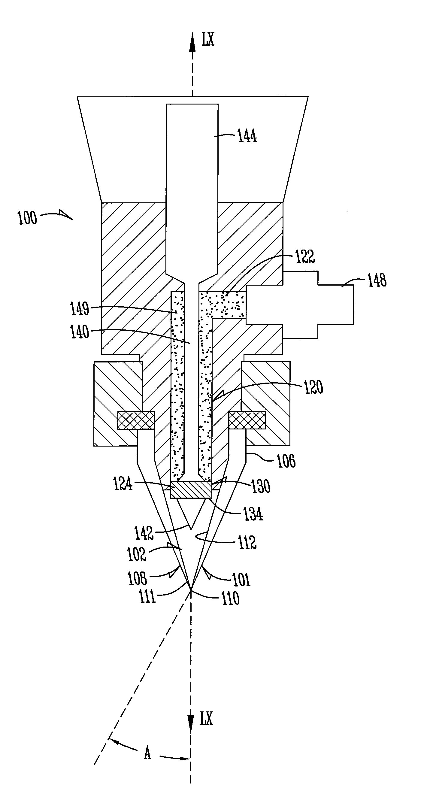
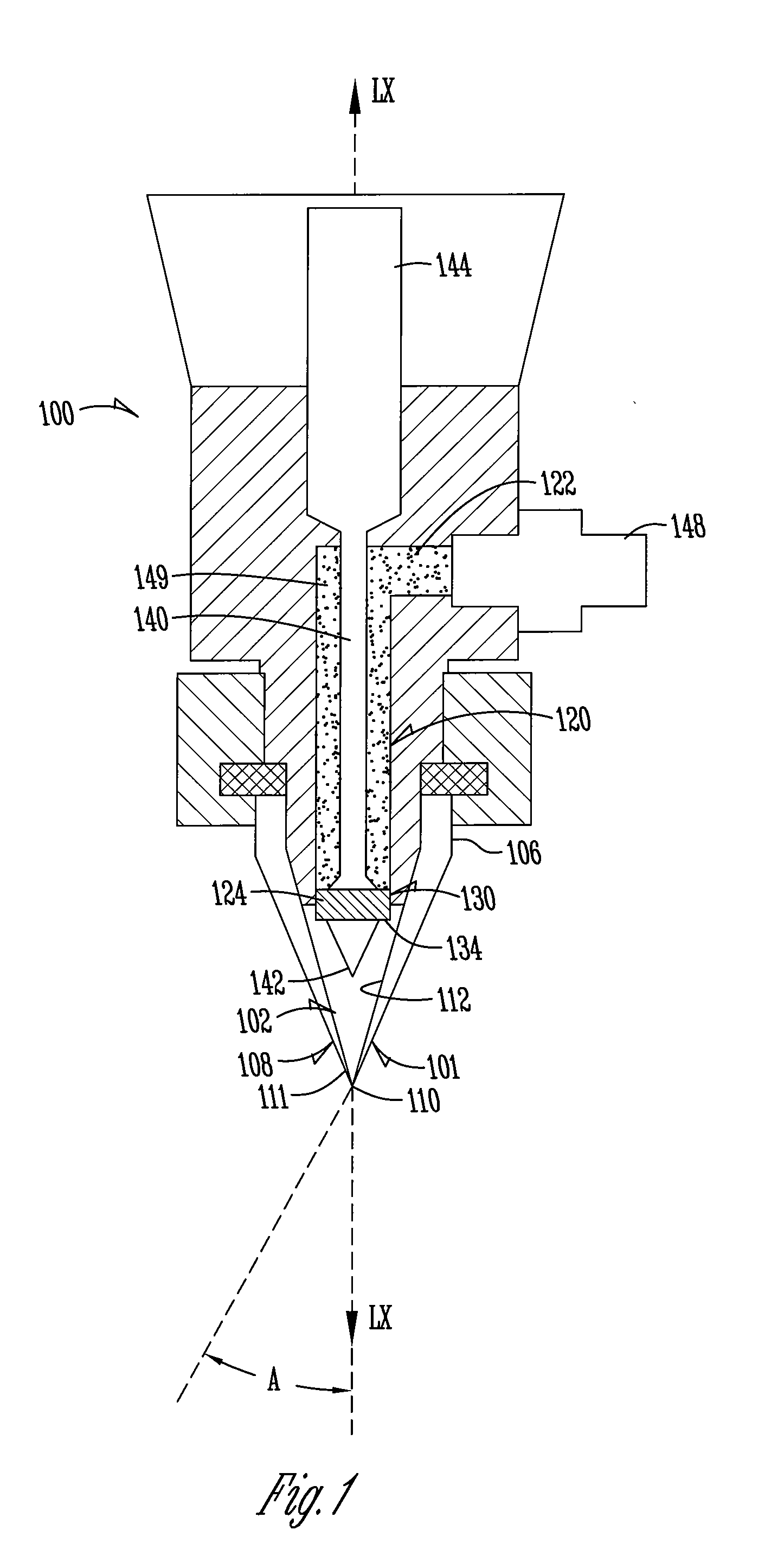
[0028]FIG. 1 illustrates one example of a material dispenser 100. The material dispenser 100 has at least one elongate feed channel 120 having an inlet 122 and a spaced outlet 124. The feed channel 120 may be...


PUM


Abstract

A method for depositing a material on a substrate includes providing an apparatus with at least one material dispenser. The method further includes positioning the pen tip at a predetermined writing gap where the predetermined writing gap is a distance of more than 75 micrometers above the substrate. The method also provides for controlling velocity of the flow of material through the outlet and dispense speed based on dispensed line height and dispensed line width parameters. An apparatus for depositing a material on a substrate is also provided which may have one or more mechanical vibrators, a pen tip with a hydrophobic surface, or multiple nozzles and pen tips on a single pump.

Description

CROSS-REFERENCE TO RELATED APPLICATIONS[0001]The present application claims priority to U.S. Provisional Patent Application No. 61 / 093,645 filed Sep. 2, 2008, herein incorporated by reference in its entirety.FIELD OF THE INVENTION[0002]The invention relates to the field of dispensing of materials, and more particularly, to methods and processes of dispensing various materials including high viscosity materials at high speeds.BACKGROUND[0003]Dispensing is a widely-used technology to apply bonding materials (e.g. adhesives, sealants and encapsulates) and functional materials (e.g. conductive, dielectric and resistive) in the electronics industry. One challenge of dispensing is to dispense a wide variety of materials on a wide range of substrates at production rate speeds. Production rate speeds are defined by standard screen printing methods.[0004]Screen printing has been accepted as an industry standard in electronic device manufacturing for many years. The advantage is the low cost ...

Claims


Application Information

Patent Timeline
IPC IPC(8): B05D5/12B05C5/00B05C11/00
CPCH01L21/67126H05K2203/0126H05K3/1241H01L21/6715
Inventor CHURCH, KENNETH H.CLARK, PATRICK A.CHEN, XUDONGOWENS, MICHAEL W.STONE, KELLY M.
Owner SCIPERIO
Learn More