Improved battery

Inactive Publication Date: 2010-03-04
INT BATTERY
View PDF26 Cites 22 Cited by
  • Summary
  • Abstract
  • Description
  • Claims
  • Application Information

AI Technical Summary

Benefits of technology

[0017]The present invention provides a low internal resistance battery cell in which the path lengths from each electrode active area to the point of connection to the terminal are equal. This equal path length creates equal electrode resistance to the terminal, a consequence of which is that current flow in each electrode of the parallel terminal circuit connection is

Problems solved by technology

However, their low energy density (about 30 wh/kg) and their inability to perform at high temperature, makes them an impractical power source for electric vehicles (EV), hybrid electric vehicles (HEV) and other systems requiring a high energy density source.
In addition, electric vehicles using lead-acid batteries have sluggish acceleration, poor tolerance to deep discharge, and a battery lifetime of only about 20,000 miles.
For example, in electric vehicles an

Method used


Image

  • Improved battery
  • Improved battery
  • Improved battery

Examples


Example

EXAMPLE

[0063]As an example, let N=9, g=0.1, t=0.05, h=1. This means that

A0=B0=d0=(N)×(g+t)−(N)×t=(N)×g=9×0.1=0.9

dn=g2

[0064]for all n from n from n=1 to n=N; dn=0.05=d1=d2=d3=d4=d5=d6=d7=d8=d9

[0065]Thus:

AN=⌊∑n=0n(dn)⌋=d0+d1+d2+d3+d4+d5+d6+d7+d8+d9=d0+9×0.05=0.9+0.45AN=1.35An=⌊∑n=0n(dn)⌋=d0+n×0.05=0.9+n×0.05

[0066]Thus:

A1=0.9+1×0.05=0.95

A2=1.0

A3=1.05

A4=1.1

A5=1.15

A6=1.2

A7=1.25

A8=1.3

A9=AN=1.35

[0067]Also:

Bn=⌊∑n=0n(dn)⌋-(n)×(g+t)B1=⌊∑n=01(dn)⌋-(1)×(g+t)=d0+d1-g-t=0.9+0.05-0.1-0.05=0.8

[0068]Similarly:

B2=B1+d2=0.85

B3=B2+d3=0.9

B4=B3+d4=0.95

B5=B4+d5=1.0

B6=B5+d6=1.05

B7=B6+d7=1.1

B8=B1+d2=1.15

B9=BN=0

[0069]Finally:

L0=L1=…=LNand:Ln=2×⌊∑n=0n(dn)⌋-(n)×(g+t)+h-(N-n)×t=L0L0=A0+B0+h-(N)×t=0.9+0.9+1-9×0.005=2.35=L1=L2=L3=L4=L5=L6=L7=L8=L9

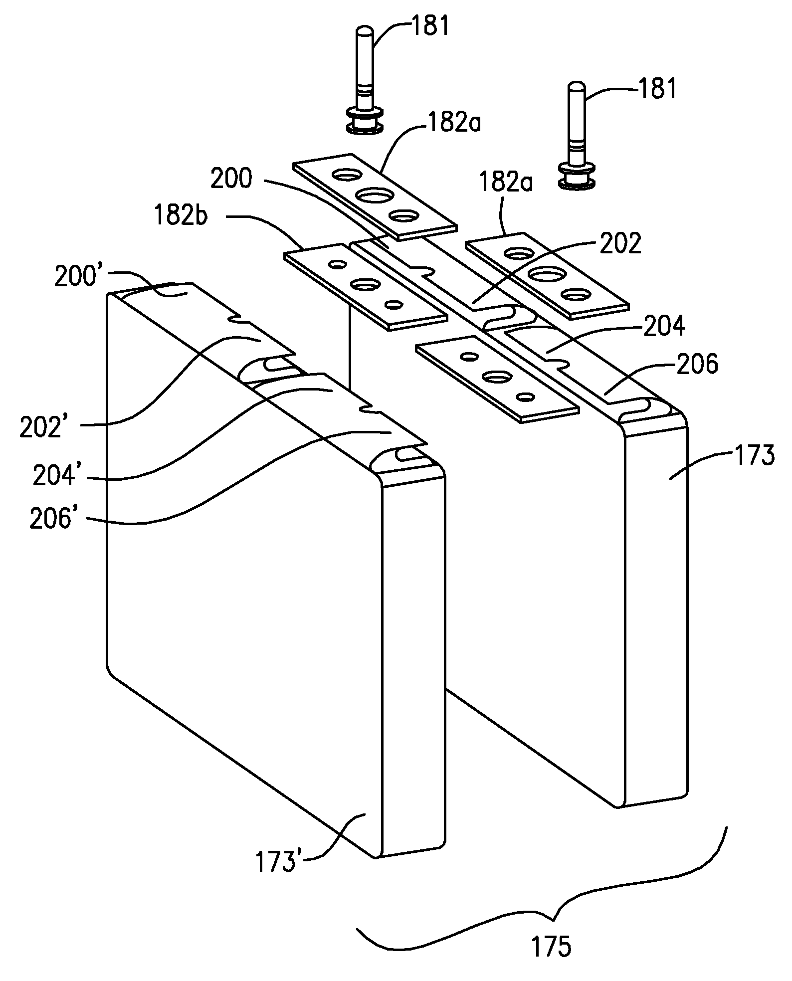
[0070]The fold geometry calculations determines a bend geometry for each electrode tab 52 in the electrode tab stack 520 that is used to fold the electrode tab stack 520 into compact, low profile, electrode tab stacks 520 characterized by flat lying, tightly folded elec...


PUM

PropertyMeasurementUnit
Lengthaaaaaaaaaa
Thicknessaaaaaaaaaa
Poweraaaaaaaaaa

Abstract

The present invention provides battery cell having low resistance internal connections and compact, low volume terminal connections in order to maximize power-producing volume. The battery of the present invention may be created using a novel fold geometry to fold electrode tabs into compact, low profile tabs having a low total volume. The battery cell provides a means for equalizing path lengths from each electrode active area to the point of connection to the terminal and also reducing path length, thereby further reducing resistance of the battery. The connection means of the present invention consumes less internal battery space than connection means of prior art electrode stacks. Accordingly, the electrode stack of the present invention disposes more or larger battery cells in the battery than the prior art and thus provides more power than the prior art battery. The present invention is designed to overcome prior art difficulties in preparing a battery.

Description

PRIORITY AND RELATED APPLICATION[0001]Not ApplicableFIELD OF THE INVENTION[0002]The present invention relates to batteries. More particularly, the present invention relates to battery containment embodiments suitable for maximizing internal space and providing maximum power output.BACKGROUND OF THE INVENTION[0003]Rechargeable batteries are used in a variety of industrial commercial and military applications such as fork lifts, uninterruptible power supplies, electric vehicles and military weapons systems.[0004]Rechargeable lead-acid batteries are a useful power source for starter motors for internal combustion engines. However, their low energy density (about 30 wh / kg) and their inability to perform at high temperature, makes them an impractical power source for electric vehicles (EV), hybrid electric vehicles (HEV) and other systems requiring a high energy density source. Electric vehicles using lead-acid batteries have a short range before requiring recharge, require about 6 to 12...

Claims


Application Information

Patent Timeline
IPC IPC(8): H01M2/26H01M50/529H01M50/534H01M50/536H01M50/541
CPCY10T29/49108H01M2/26Y02E60/10H01M50/531H01M50/536H01M50/534
Inventor MESCHTER, JOHN ERIC
Owner INT BATTERY
Why Eureka
Try Eureka