
Tubular-member flange coupling

Inactive Publication Date: 2010-03-11
MITSUBISHI HEAVY IND LTD
View PDF17 Cites 18 Cited by
  • Summary
  • Abstract
  • Description
  • Claims
  • Application Information

AI Technical Summary

Benefits of technology

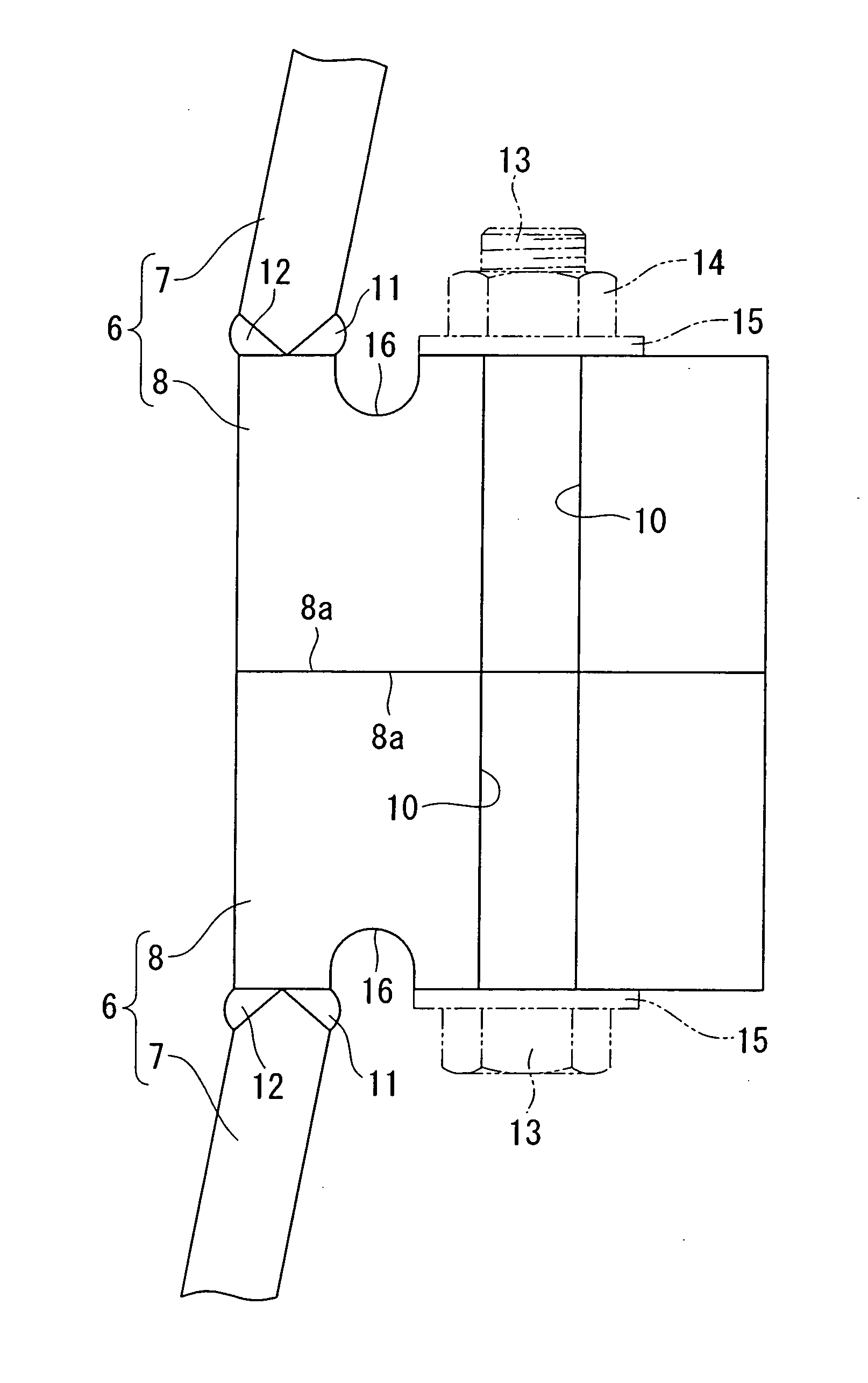
[0006]The present invention has been made in view of such circumstances, and an object thereof is to provide a tubular-member flange coupling capable of shortening the production process and reducing the manufacturing costs.
[0017]The present invention provides advantages in that the production process can be shortened and the manufacturing costs can be reduced.

Problems solved by technology

Therefore, there are problems in that the production process is prolonged and the manufacturing costs increase.

Method used


Image

  • Tubular-member flange coupling
  • Tubular-member flange coupling
  • Tubular-member flange coupling

Examples


Embodiment Construction

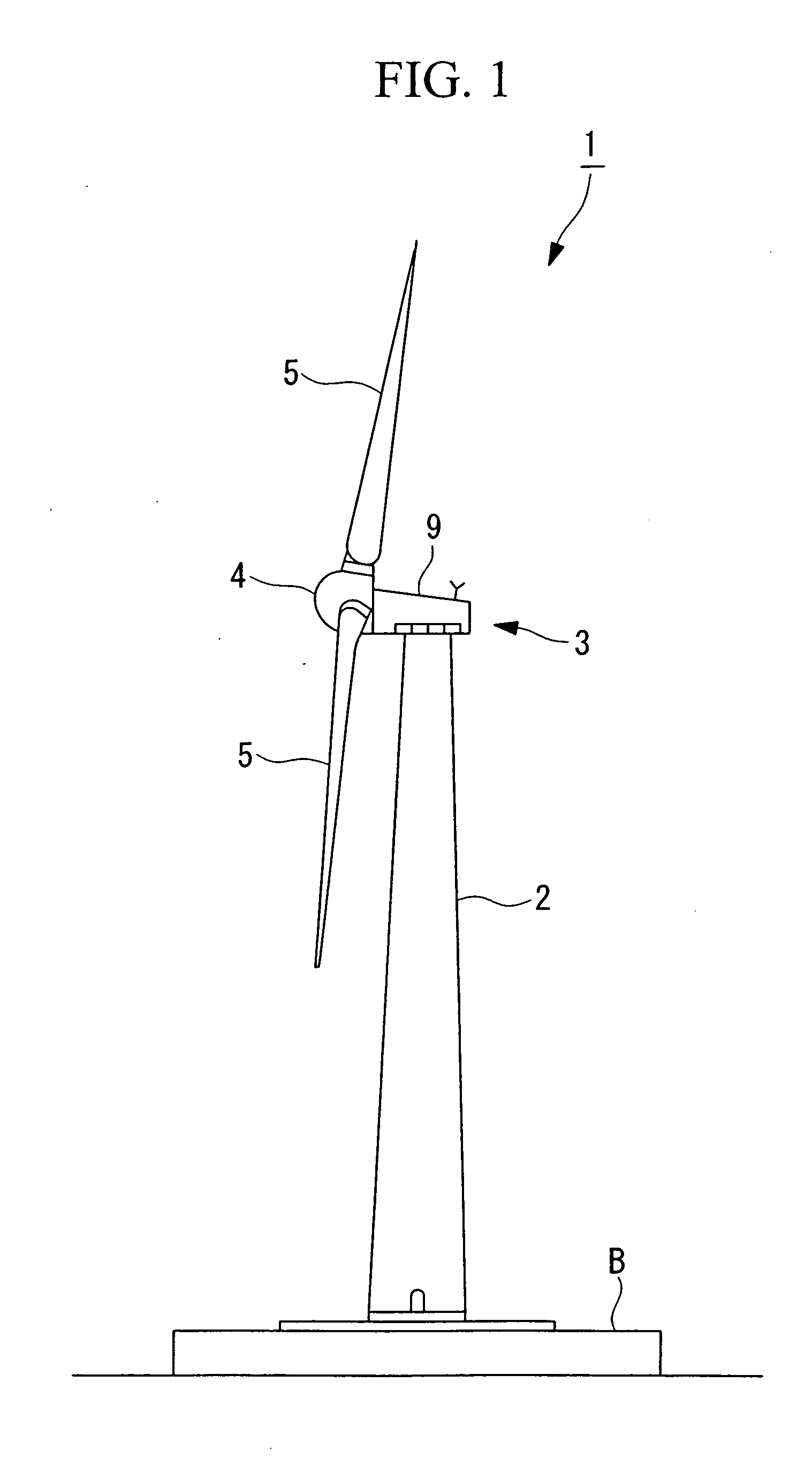
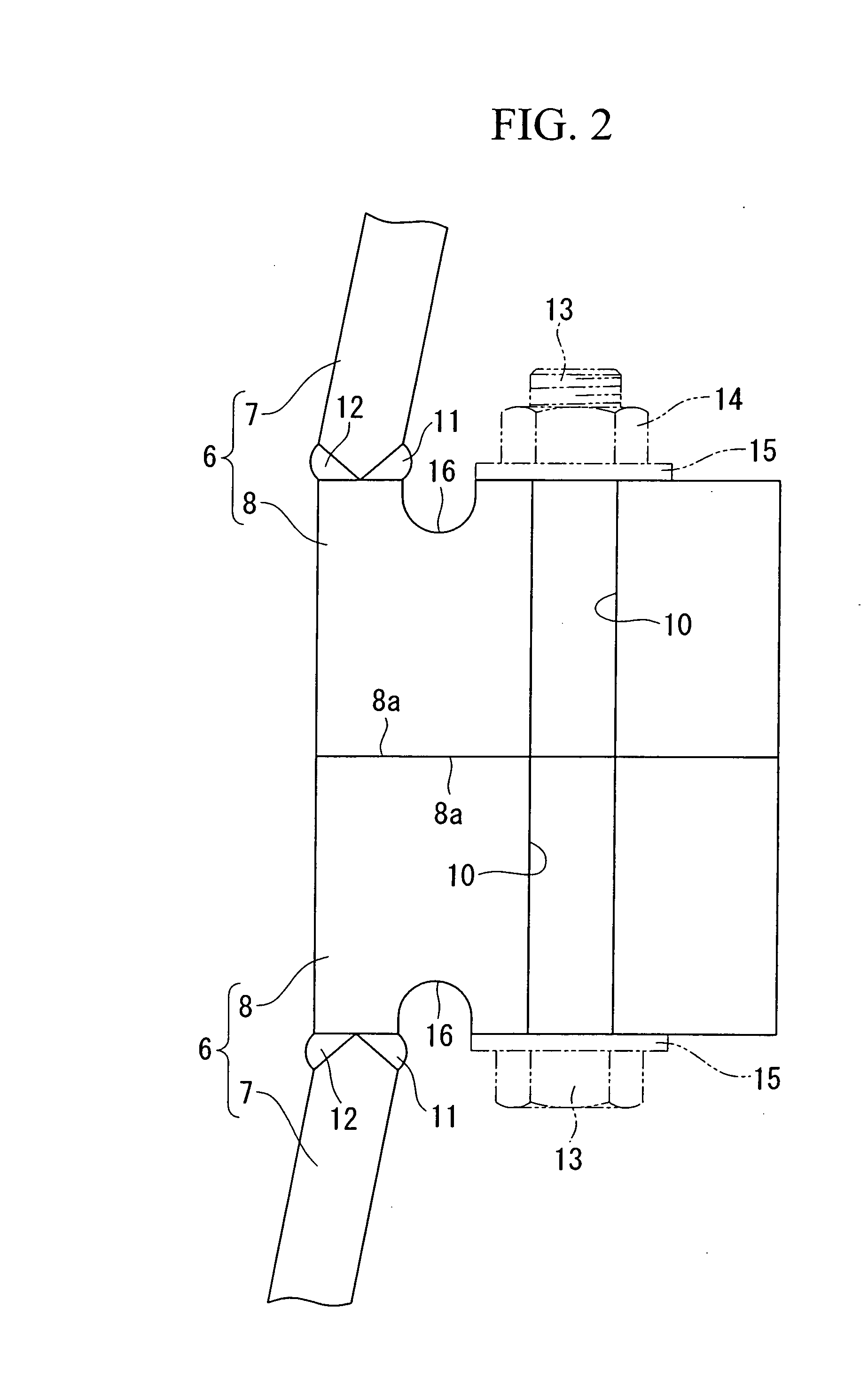
[0033]A ring-shaped-member flange coupling (hereinafter, “flange coupling”) according to an embodiment of the present invention will be described below with reference to FIGS. 1 and 2.

[0034]FIG. 1 is a side view of a wind turbine for wind turbine generator having flange couplings according to this embodiment, and FIG. 2 is a longitudinal sectional view of a relevant part in FIG. 1.

[0035]As shown in FIG. 1, the wind turbine for wind turbine generator 1 includes a support tower (also referred to as “tower”) 2 installed upright on a foundation B, a nacelle 3 mounted on the top of the support tower 2, and a rotor head 4 mounted to the nacelle 3 so as to be rotatable about a substantially horizontal axis.

[0036]A plurality of (for example, three) wind turbine rotor blades 5 are radially attached around the rotation axis of the rotor head 4. Thus, the force of the wind blowing in the rotation axis direction of the rotor head 4 against the wind turbine rotor blades 5 is converted into motiv...


PUM


Abstract

The production process is shortened and the manufacturing costs are reduced. The present invention is a tubular-member flange coupling (8) in which a top or bottom end of a circumferential portion is mated to a bottom or top end of a tubular member (7) to couple the tubular members (7) to each other. A recess (16) having a substantially U-shape in cross-section is provided around a circumferential direction in a surface to be connected to the tubular member (7) at a position radially inward of a surface to be mated to the tubular member (7).

Description

TECHNICAL FIELD[0001]The present invention relates to, for example, a tubular-member flange coupling for connecting (coupling or joining) tubular members constituting a support tower of a wind turbine for wind turbine generator.BACKGROUND ART[0002]As a tubular-member flange coupling for connecting tubular members constituting a support tower of a wind turbine for wind turbine generator, for example, one disclosed in Patent Document 1 is known.[0003]Patent Document 1:[0004]Japanese Translation of PCT International Application, Publication No. 2004-525293DISCLOSURE OF INVENTION[0005]However, in the tubular-member flange coupling disclosed in Patent Document 1, a tubular portion to be connected (coupled or joined) to the bottom or top end of a tubular member via a weld seam is produced by cutting. Therefore, there are problems in that the production process is prolonged and the manufacturing costs increase.[0006]The present invention has been made in view of such circumstances, and an ...

Claims


Application Information

Patent Timeline
IPC IPC(8): E04H12/08
CPCE04H12/085E04H12/08
Inventor NUMAJIRI, TOMOHIRO
Owner MITSUBISHI HEAVY IND LTD
Learn More