

Photoacoustic apparatus
a technology of acoustic equipment and acoustic wave, which is applied in the field of photoacoustic equipment, can solve the problems of insufficient intensity of acoustic wave generated in the deep region of the organism, and difficulty in obtaining spectrum information of a specific si
- Summary
- Abstract
- Description
- Claims
- Application Information
AI Technical Summary
Benefits of technology
Problems solved by technology
Method used
Image

Examples
first embodiment
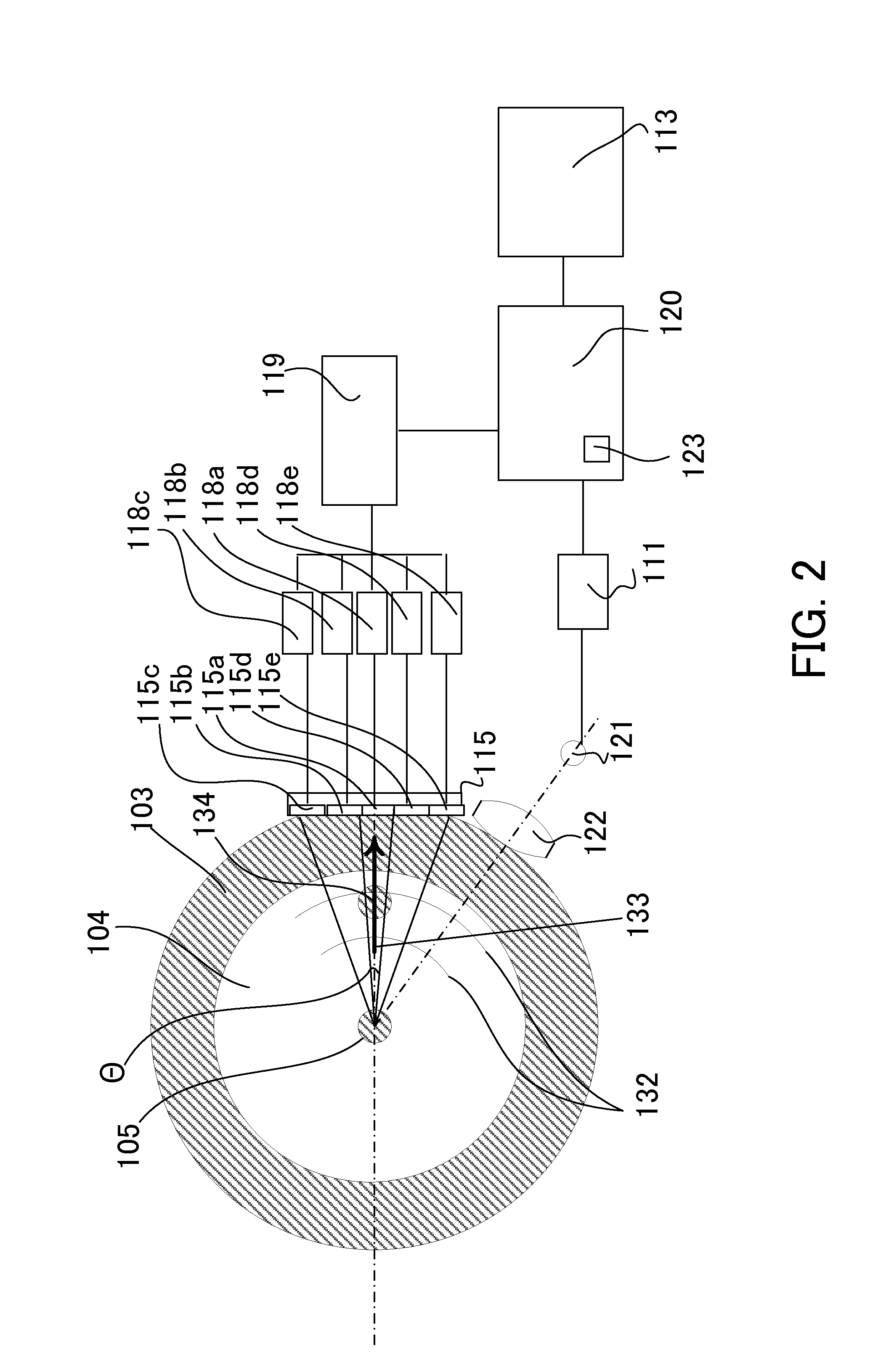
[0024]A detailed description will now be given of the visualization technology of the inside of the organism using the photoacoustic method as a comparative example.
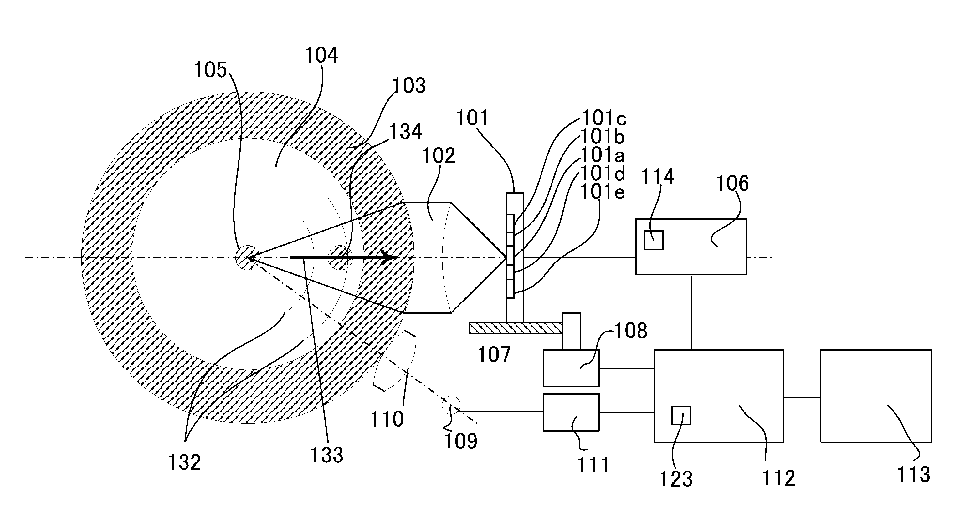
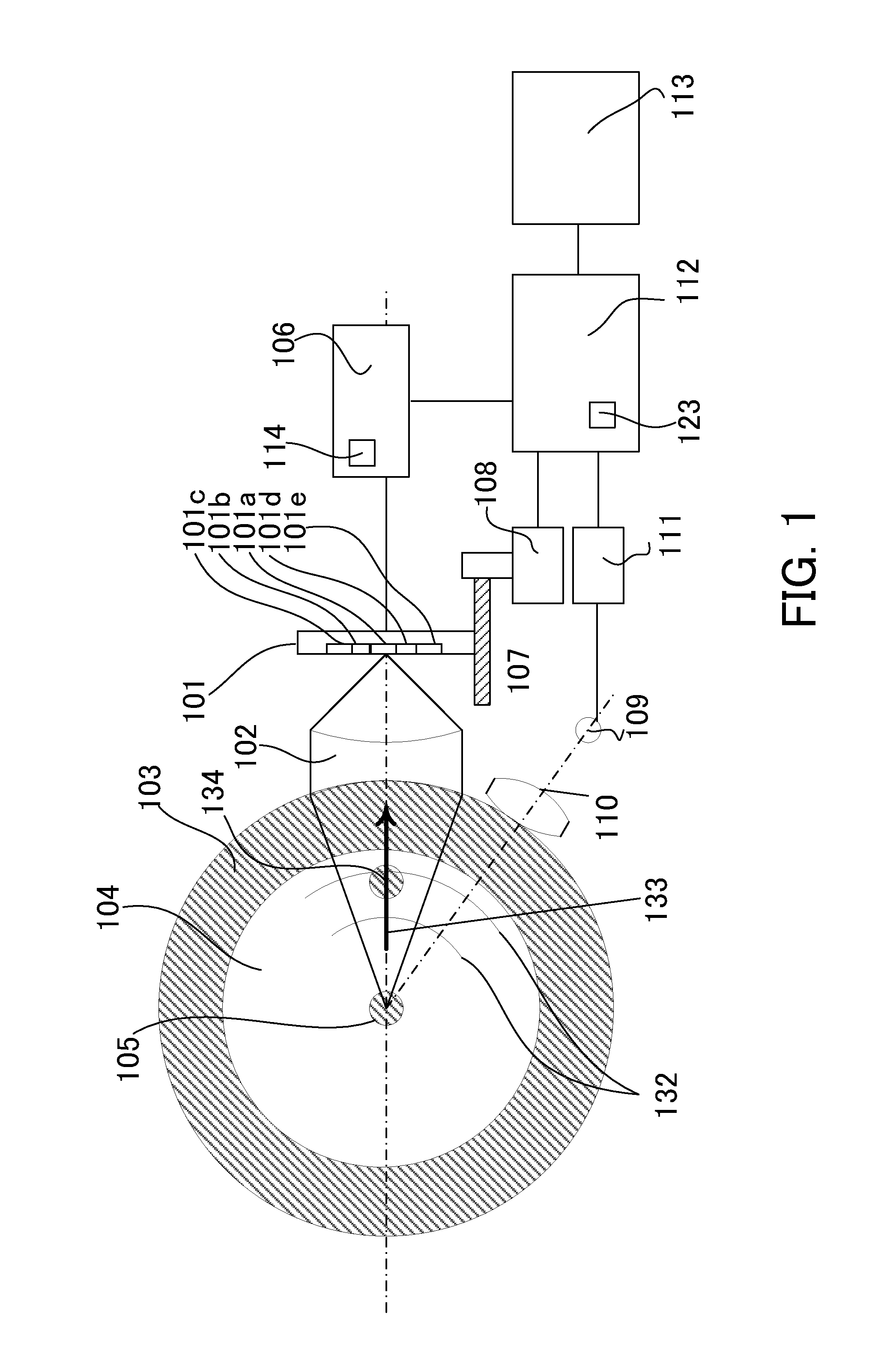
[0025]FIG. 2 shows an overview of the photoacoustic method as a comparative example. An object 104 to be measured is an organism, and contains an absorber (first absorbing region) 105 that absorbs the near infrared light and is located at a first position. A matching layer (or matching solution) 103 makes the optical characteristic of the object 104 and that of the near infrared light approximately equal to each other for smooth propagations of the light and acoustic wave. The acoustic wave in this embodiment means an elastic wave that occurs in the object to be measured when the light, such as the near infrared ray, is irradiated onto the object, and the acoustic wave covers a sound wave, an ultrasonic wave, and a photoacoustic wave.
[0026]The light source 121 is a light source that irradiates pulsed light of the nanosec...
second embodiment
[0091]A description will be given of a second embodiment according to the present invention. FIG. 8 is a view for explaining the second embodiment. This embodiment configures the apparatus of the first embodiment to be an array structure, and detects an absorber 205 in an object 204 by using the photoacoustic effect.
[0092]Reference numerals 202a, 202b, and 202c denote an array of two-dimensionally arranged acoustic lenses, for which a corresponding one of array type acoustic detectors 201a, 201b, and 201c and a corresponding one of array type drivers 206a, 206b, and 206c are provided. Reference numerals 208a, 208b, and 208c denote acoustic transducer drivers, and reference numerals 207a, 207b, and 207c denote driver controllers.
[0093]The principle is similar to that of the first embodiment, and a description thereof will be omitted.
[0094]A light source 209 emits pulsed light of the nanosecond order via an illumination optical system 210. The acoustic wave generated from the absorber...
third embodiment
[0099]Referring to FIG. 11, a description will be given of a third embodiment according to the present invention. FIG. 11 shows an illustrative structure of an apparatus configured to obtain the acoustic image utilizing the approach described in the first embodiment.
[0100]A housing 310 is a housing configured to house an acoustic transducer 301 and a light source 308, and an observer utilizes the housing 310 and obtains an acoustic image in an object 304 to be measured, which is for example, a human breast. The light does not go straight in the object 304 due to the strong scattering characteristic to the near infrared light although the absorption characteristic is not so strong.
[0101]The light source 308 is a light source configured to emit pulsed light of the near infrared light, and connected to a controller 311 via the light source driver 313. The controller 311 has a memory 123, configured to store an acoustic image etc. The light emitted form the light source 308 illuminates ...
PUM
 Abstract
Description
Claims
Application Information