Solar cell module

a solar cell module and solar cell technology, applied in the field of solar cell modules, can solve the problems of high possibility of damage to the frameless module, achieve the effects of preventing the damage of the solar cell module, enhancing the strength of the frame 105 holding, and reducing the displacement of the light-receiving surface protection member 101

Inactive Publication Date: 2010-03-11
SANYO ELECTRIC CO LTD
View PDF3 Cites 7 Cited by
  • Summary
  • Abstract
  • Description
  • Claims
  • Application Information

AI Technical Summary

Benefits of technology

[0007]One of methods having been heretofore devised to prevent the damage of the solar cell module 100 is to enhance the strength of a frame 105 holding the solar cell module 100 and thereby to reduce the displacement of the light-receiving-surface protection member 101. However, there is a report on the damage of the solar cell module 100 which is peculiar to a portion held by the frame 105.

Problems solved by technology

Even though elaborately packaged, such a frameless module is highly possibly damaged during transportation at corner portions of the solar cell module 100, particularly at corner portions (W1 and W2 in FIG. 3) of the light-receiving-surface protection member 101 located on the upper side thereof.

Method used


Image

  • Solar cell module
  • Solar cell module
  • Solar cell module

Examples


first embodiment

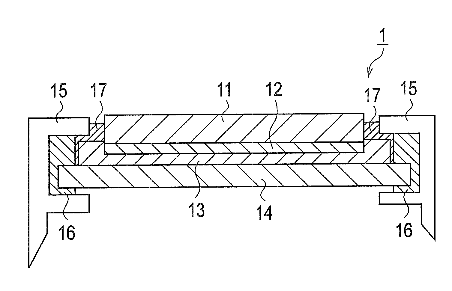
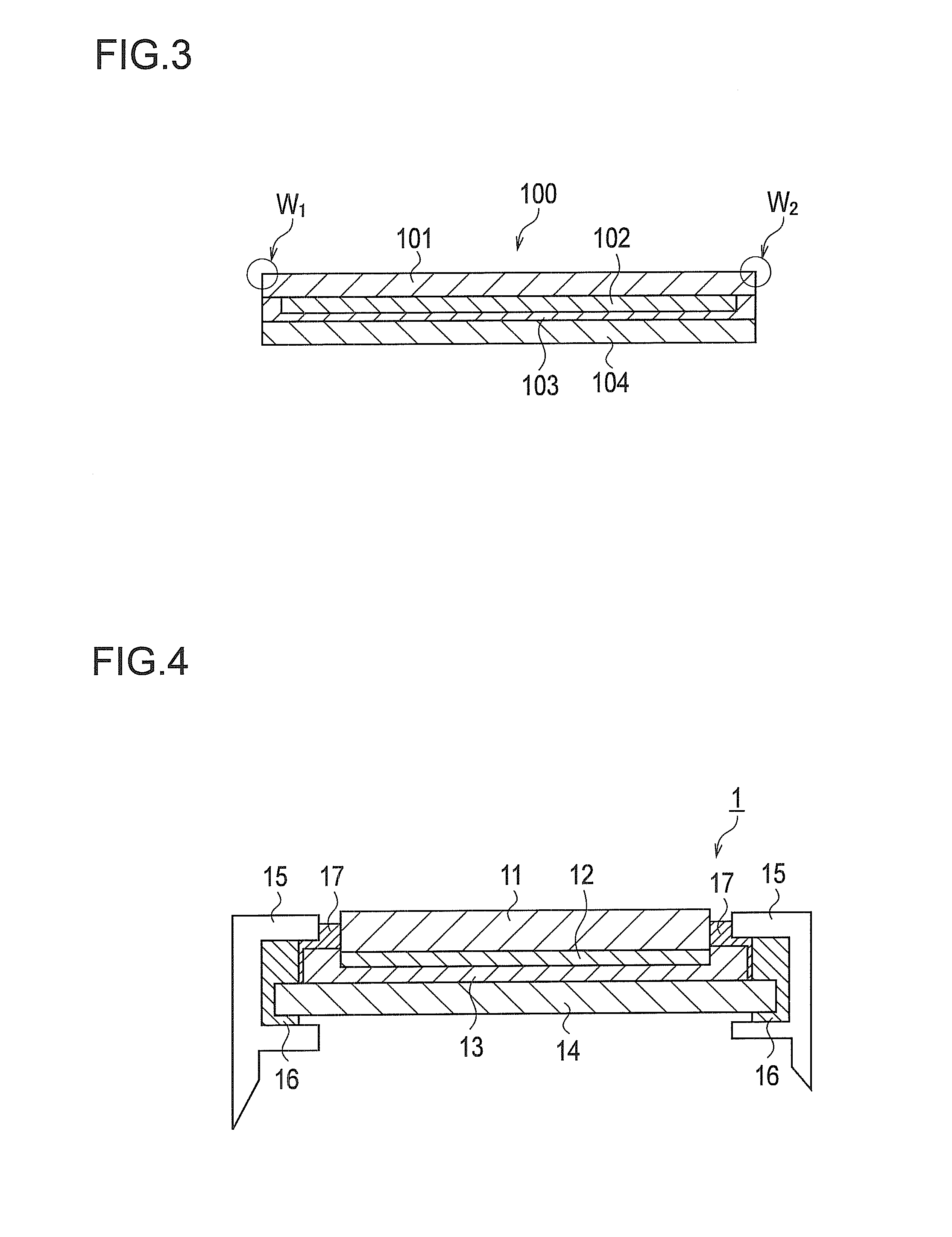
[0028]By using FIG. 4 to FIG. 7, a description will be given of a solar cell module shown as an embodiment of the present invention.

[0029]As shown in FIG. 4, in a solar cell module 1, a solar cell layer 12 is formed on a light-receiving-surface protection member 11. The light-receiving-surface protection member 11 includes a light-receiving surface and a rear surface provided on a side opposite to the light-receiving surface.

[0030]The light-receiving surface of the light-receiving-surface protection member 11 is made of a glass plate (blue plate glass, for example). The rear surface of the light-receiving-surface protection member 11 is composed of a SnO2 (tin oxide) layer formed on the glass plate by a thermal CVD method. The SnO2 layer serves as a transparent electrode.

[0031]The solar cell layer 12 is formed on the rear surface (SnO2 layer) of the light-receiving-surface protection member 11. The solar cell layer 12 is composed of a semiconductor layer formed on the SnO2 layer, an...

second embodiment

(Modification of Second Embodiment)

[0059]Next, a modification of the second embodiment will be described with reference to the drawing.

[0060]In a solar cell module 3 shown in FIG. 9, the end surfaces 11b of the light-receiving-surface protection member 11 and end surfaces 13b of the filling member 13 are protected by the covering member 17. Moreover, the bonding member 16 used for bonding the rear-surface protection member 14 to the frame 15 covers the cover portions 11c of the light-receiving-surface protection member 11. In other words, in the solar cell module 3, the corner portions 11c of the light-receiving-surface protection member 11 are covered with the bonding member 16. As similar to the solar cell module 2 shown in FIG. 7 and FIG. 8, the bonding member 16 which covers the region S (see FIG. 8) preferably does not overlap the solar cell layer 12.

[0061]The resin materials described above can be used as the filling member 13, the bonding member 16 and the covering member 17....

third embodiment

(Modification of Third Embodiment)

[0067]The solar cell module 4 shown in FIG. 10 has been described on the basis of the structure of the solar cell module 2 shown in FIG. 7. Alternatively, the solar cell module 4 may have a structure based on the solar cell module 3 shown in FIG. 9. To be more specific, the end surfaces 11b of the light-receiving-surface protection member 11 and the end surfaces 13b of the filling member 13 may be protected by the covering member 17. Moreover, the bonding member 16 which is used for fixing the frame 15 holding the rear-surface protection member 14 may be filled between the protection portion 15a of the frame 15 and the outer edge portion of the light-receiving-surface protection member 11.

Other Embodiments

[0068]In the embodiments described thus far, blue plate glass is used as the light-receiving-surface protection member 11, whereas blue plate tempered glass is used as the rear-surface protection member 14. However, the present invention is not lim...


PUM


Abstract

A solar cell module 1 includes a transparent light-receiving-surface protection member 11, a rear-surface protection member 14 placed at the rear surface side of the light-receiving-surface protection member 11, and a plurality of solar cells bonded between the light-receiving-surface protection member 11 and the rear-surface protection member 14. The rear-surface protection member 14 has a planar shape larger than that of the light-receiving-surface protection member. Further, the rear-surface protection member 14 has a smaller amount of displacement for an external load than that of the light-receiving-surface protection member, or has higher strength against impact than that of the light-receiving-surface protection member.

Description

TECHNICAL FIELD[0001]The present invention relates to a solar cell module including a light-receiving-surface protection member and a rear-surface protection member.BACKGROUND ART[0002]Solar cells can directly convert sunlight, which is a clean and unlimitedly-supplied energy source, into electricity, and thus are expected as one of new energy sources. As such a solar cell, the development of a thin-film solar cell has been in progress. The thin-film solar cell is mainly composed of a thin film semiconductor material such as an amorphous silicon semiconductor, a microcrystalline silicon semiconductor or CuInSe.[0003]As an example of such a thin-film solar cell, a structure of a conventional solar cell module using an amorphous silicon thin-film solar cell will be described with reference to FIG. 1 (see JP-A 11-135811, for example).[0004]A solar cell module 100 includes a light-receiving-surface protection member 101, a solar cell layer 102, a resin material 103 such as EVA or PVB, a...

Claims


Application Information

Patent Timeline
Patent Type & Authority Applications(United States)
IPC IPC(8): H01L31/042
CPCY02E10/50H01L31/048H01L31/049
Inventor YAGIURA, TOSHIOOGASAHARA, SATORU
Owner SANYO ELECTRIC CO LTD
Why Eureka
Try Eureka