
Device and method for the treatment of skin, and use of the device

Active Publication Date: 2010-03-11
KONINKLIJKE PHILIPS ELECTRONICS NV
View PDF18 Cites 27 Cited by
  • Summary
  • Abstract
  • Description
  • Claims
  • Application Information

AI Technical Summary

Benefits of technology

[0008]The device according to the invention is able to provide a laser induced optical breakdown (LIOB) phenomenon in the skin by providing sufficiently intense laser pulses. This LIOB is based on strong non-linear absorption of the laser light by the skin tissue, which occurs above a certain threshold value for the power density of the laser light. This strong absorption causes a very localized plasma that is able to damage or even remove tissue at the location of said plasma. This is caused by secondary, primarily mechanical effects such as rapid expansion of the generated plasma. This effect is very local, because below the threshold, there is zero or very little linear and non-linear absorption, while above the threshold a plasma is generated, which even more strongly absorbs the radiation. In other words, effects such as LIOB only occur at the focal spot, while above and below the focal spot no or very much weaker effects occur. This means that for example the epidermis may easily be safeguarded against undesired effects or damage. Another safety feature against damage to the epidermis is the fact that LIOB is very efficient. A very limited amount of energy is needed to obtain the desired local effects.
[0032]The invention also relates to the use of a device according to the invention in the treatment of skin, in particular non-invasive wrinkle reduction in the skin. This aspect uses the advantage that LIOB has in treating skin, i.e. it can provide small amounts of energy very locally, and at a desired depth without affecting the layers above. The use is thus inherently safe in particular in comparison to other treatments that apply electromagnetic radiation.

Problems solved by technology

A very limited amount of energy is needed to obtain the desired local effects.

Method used


Image

  • Device and method for the treatment of skin, and use of the device
  • Device and method for the treatment of skin, and use of the device
  • Device and method for the treatment of skin, and use of the device

Examples


Embodiment Construction

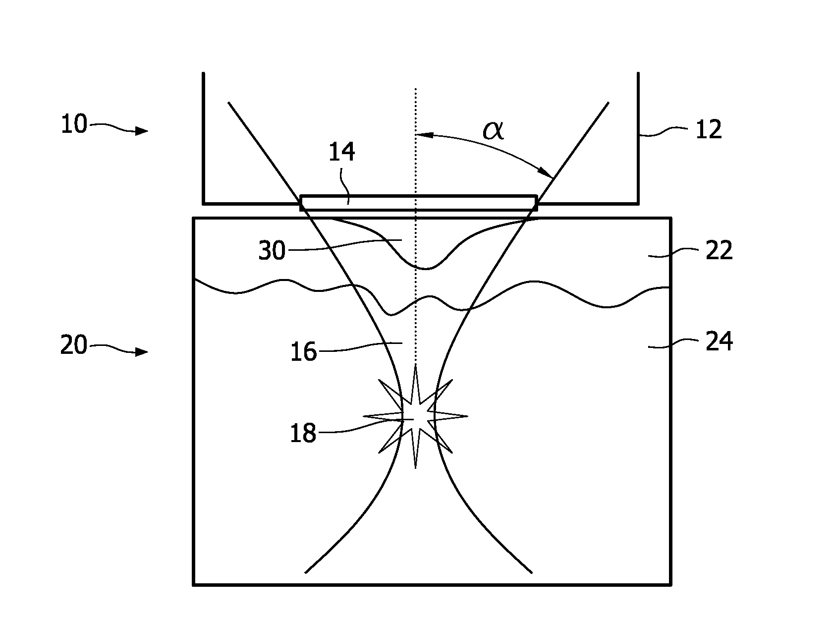
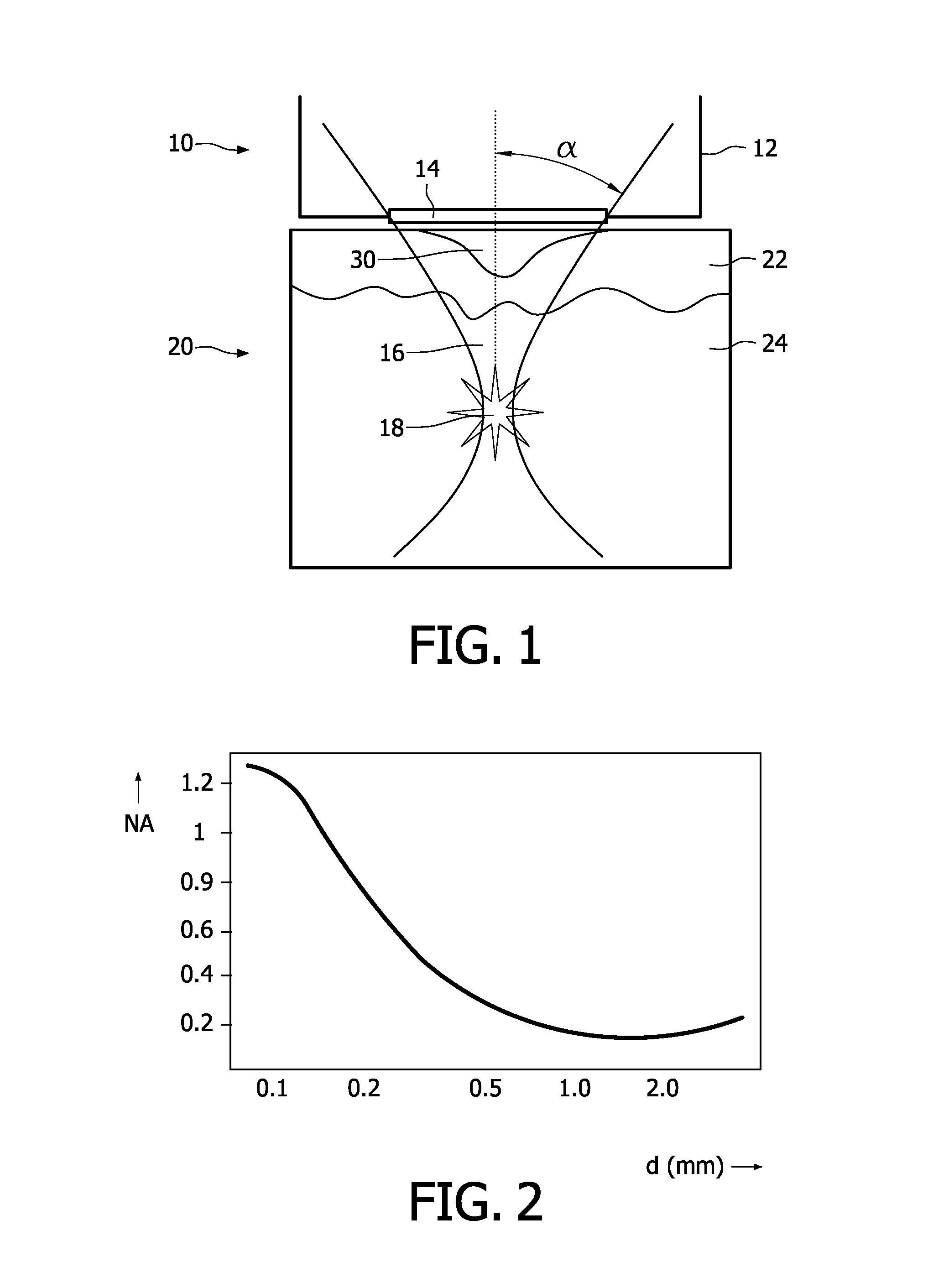
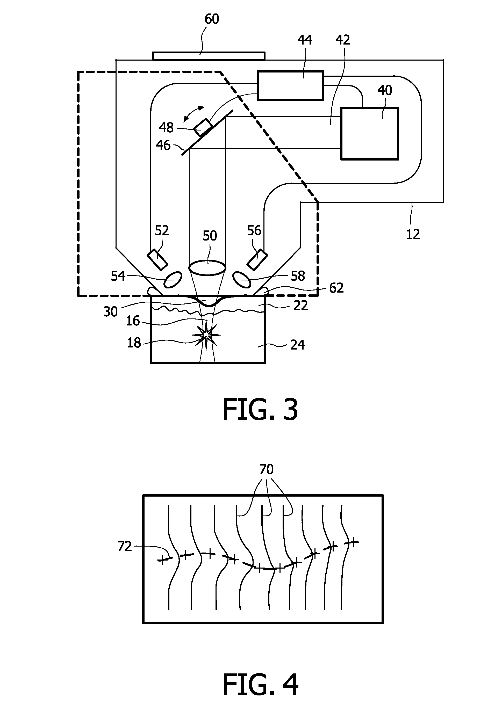
[0037]FIG. 1 diagrammatically shows the most important parts of the device in use when treating skin. By means of reference numeral 10, a part of the device is designated, while 20 designates skin to be treated. The device 10 comprises a housing 12 with a laser beam exit window 14, through which a laser beam 16 is emitted that is focused in a focal spot 18.

[0038]The skin 20 comprises an epidermis 22 and a dermis 24. The skin 20 has a wrinkle 30, which is filled with an index-matching medium.

[0039]In use, the device 10, or at least the part shown here, is applied to the skin 20. A laser beam 16 is emitted through the laser beam exit window 14, which may be made of a transparent material or may simply be an aperture in the housing 12. However, a window of a transparent material has the advantage that it better defines the position of the skin 20 with respect to the device 10.

[0040]The laser beam 16 roughly resembles a hyperboloid with an apical angle α and a waist or focal spot 18. Th...


PUM


Abstract

The invention provides a skin treatment device comprising a laser source (40) and focusing optics (50), such that a focal spot (18) is positioned in a dermis layer (24) of the skin to be treated. The laser beam (42) is powered and focused (16) such that a LIOB (laser induced optical breakdown) phenomenon is obtained, which affects the skin in order to stimulate re-growth of tissue. This in turn reduces wrinkles (30). The device may comprise wrinkle-determining means (52, 54, 56, 58). The focusing optics (50) may have a numerical aperture of at least 0.4. The invention also provides a corresponding method to treat skin, in particular to reduce wrinkles (30), by providing a focused laser beam (16) that causes LIOB in the dermis layer (24) of the skin. The advantage is that damage to overlaying epidermis layers may be avoided by the use of the very local LIOB phenomenon.

Description

FIELD OF THE INVENTION[0001]The present invention relates generally to the treatment of skin using electromagnetic radiation. More particularly, the invention relates to a device and method for the treatment of skin, more particularly non-invasive wrinkle reduction of the skin. The invention furthermore relates to the use of a device in the treatment of skin.BACKGROUND OF THE INVENTION[0002]The desire to maintain a youthful appearance by preventing or reducing wrinkles in the skin is an important issue in human society. Many techniques have been designed to achieve the above goal. One of the techniques is to damage part of the dermis of the skin in order to induce the formation of connective tissue and new epidermis of the skin. Document U.S. Pat. No. 5,964,749 discloses a method and apparatus for wrinkle smoothing by applying pulsed light to the skin to heat and shrink collagen. In certain embodiments, light with a wavelength in the range of 600-1200 nm is applied, in the form of p...

Claims


Application Information

Patent Timeline
IPC IPC(8): A61B18/18
CPCA61B5/1077A61B5/442A61B18/20A61B18/203A61B19/5212A61B2017/00057A61B2018/2085A61B2017/00154A61B2018/00452A61B2018/0047A61B2018/00666A61B2018/00904A61B2017/00106A61B90/361A61B2018/20351A61B2018/20361
Inventor VERHAGEN, RIEKOVAN HAL, ROBBERT A.M.GOTTENBOS, BARTJANSSEN, JOZEF J.M.ACKERMANS, PAUL A.J.MORALES SERRANO, FRANCISCONERKEN, SIEGLINDEBROKKEN, DIRKROOSEN, GUIDO
Owner KONINKLIJKE PHILIPS ELECTRONICS NV
Learn More