Sealed and pressurized gun for underwater welding

Inactive Publication Date: 2010-03-18
NELSON STUD WELDING
View PDF15 Cites 7 Cited by
  • Summary
  • Abstract
  • Description
  • Claims
  • Application Information

AI Technical Summary

Benefits of technology

[0008]In one aspect there is disclosed an underwater fastener welding apparatus that includes a welding tool positioned within a watertight housing. The housing includes an inlet coupled to a source of pressurized gas. The housing is pressurized to balance a pressure internal to and external to the housing when the underwater welding apparatus depth level is chan

Problems solved by technology

The pressure of the water pushing against the spring in the gun may obstruct or even

Method used


Image

  • Sealed and pressurized gun for underwater welding
  • Sealed and pressurized gun for underwater welding
  • Sealed and pressurized gun for underwater welding

Examples


examples

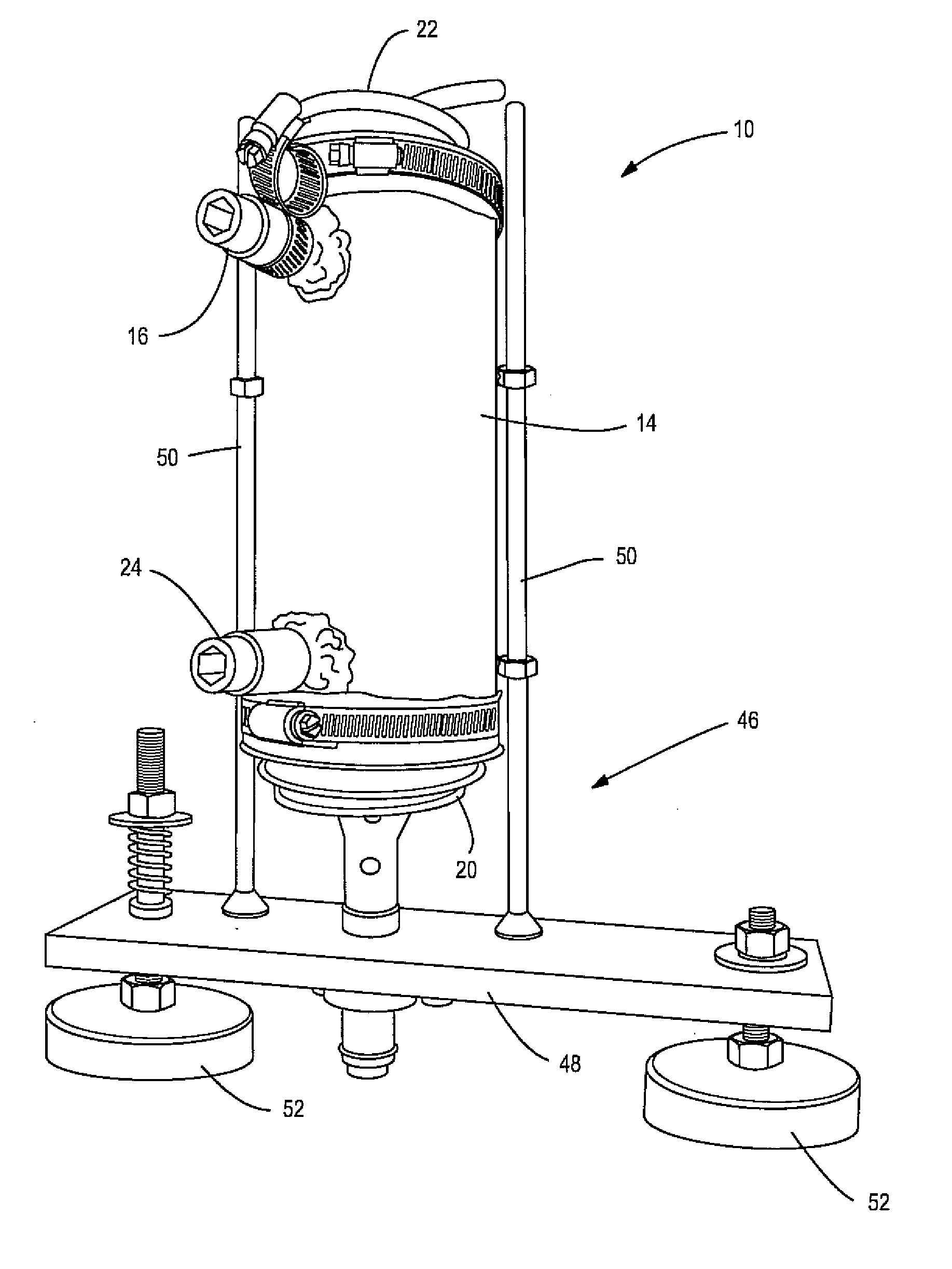
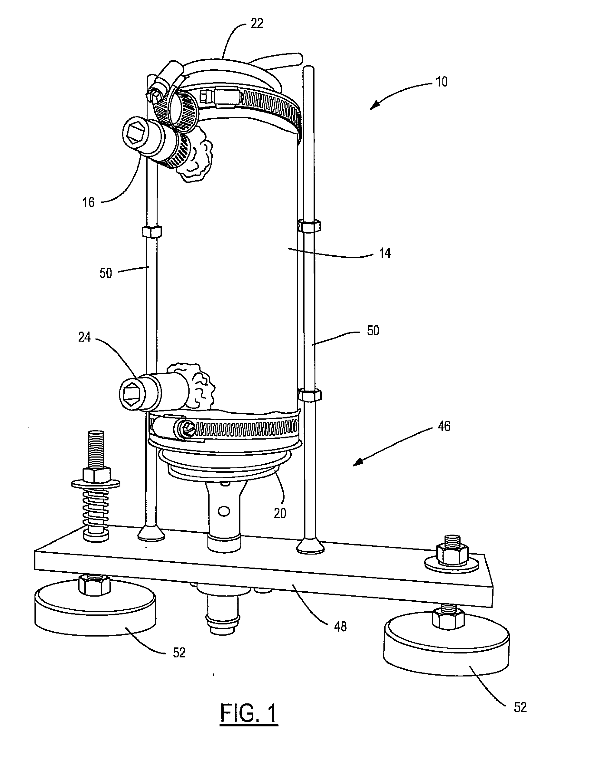
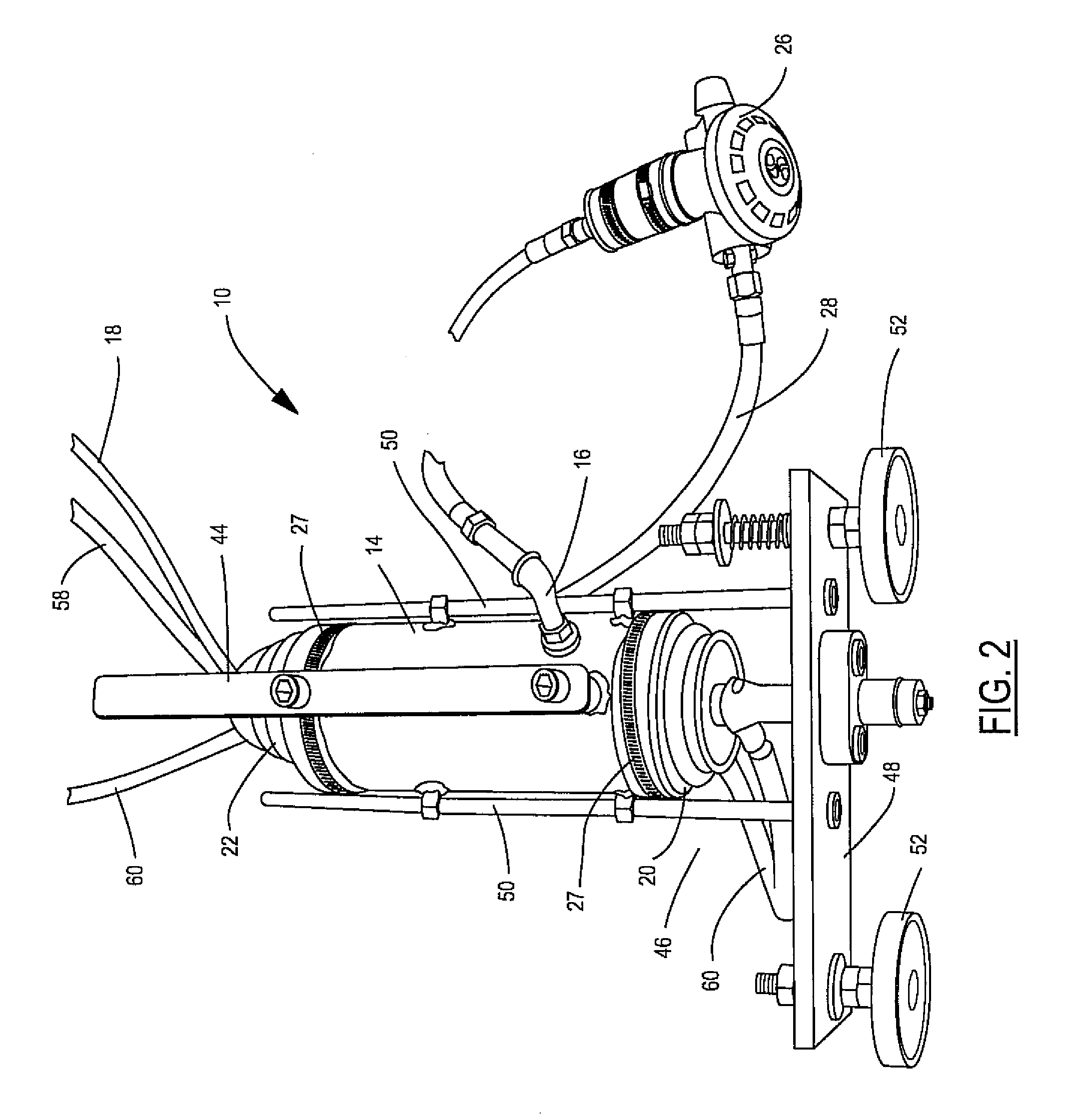
[0032]A Nelson™ Heavy Duty Gun, as shown in FIG. 6 was encapsulated in a housing. A seal formed of a suitable material such as rubber and having a boot or bellows was used to seal opposing ends of the housing. An inlet in the housing provided entry of a source of pressurized gas and was attached to a scuba regulator (a Scuba Pro II Stage G250HP in the S600 / 600P version). The regulator was attached to the housing a high pressure line to which was provided high pressure air supplied at 150 psi from a tank or compressor. The regulator increased the pressure inside the gun to match the pressure as the depth was increased. The pressurization of the gun allowed the lift and plunge to take place normally and was not affected by a depth of the underwater stud welding gun. From the example described above, the depth of the tank that the testing was conducted was at 18 feet of depth.

[0033]The foot assembly was attached to the housing and applied to a work piece that was positioned at 18 feet ...


PUM

PropertyMeasurementUnit
Pressureaaaaaaaaaa
Sizeaaaaaaaaaa
Volumeaaaaaaaaaa

Abstract

An underwater fastener welding apparatus that includes a welding tool positioned within a watertight housing. The housing includes an inlet coupled to a source of pressurized gas. The housing is pressurized to balance a pressure internal to and external to the housing when the underwater welding apparatus depth level is changed.

Description

CROSS-REFERENCE TO RELATED APPLICATIONS[0001]This application claims priority benefit of U.S. provisional patent application No. 61 / 086,907 filed on Aug. 7, 2008 and is herein incorporated by reference.FIELD OF THE INVENTION[0002]The invention relates to underwater stud welding guns and underwater assemblies for stud welding guns.BACKGROUND OF THE INVENTION[0003]Underwater welding may be performed to attach or connect various components. There is a need in the art for an improved stud welding gun that will function normally in an underwater environment.[0004]The external pressure that is exerted on any submerged object varies with the depth of the water. In fresh water the pressure is 0.432 psi per foot of depth. In salt water the pressure is 0.445 psi per foot of depth. The depth of the water and the compressible area of the gun that that is exposed to the water will determine the total force that will be applied against a spring inside the gun that actuates a stud or component in ...

Claims


Application Information

Patent Timeline
IPC IPC(8): B23K37/00B23K9/20
CPCB23K9/0061B23K11/26B23K11/0053B23K9/20
Inventor CHAMPNEY, CLARK
Owner NELSON STUD WELDING
Why Eureka
Try Eureka