Heating system

a heating system and heating technology, applied in the field of floors, can solve the problems of laborious and expensive installation of this type of system, inability to use a technique during a remodeling project, and high cost of installation

Active Publication Date: 2010-03-18
UNITED STATES GYPSUM CO
View PDF15 Cites 29 Cited by
  • Summary
  • Abstract
  • Description
  • Claims
  • Application Information

AI Technical Summary

Benefits of technology

[0028]In an embodiment, a multi-functional layer may be included in the multilayer panel that is adhered to the radiant heater using a second adhesive. The multi-functional layer of may be thermal insulation, sound suppression material, waterproofing material, electrical insulation or crack isolation material. The multi-functional layer may be one of a low density foam, a polymeric sheet, a rubber sheet or combinations thereof.

Problems solved by technology

This technique also cannot be used during a remodeling project unless a homeowner is willing to replace the subfloor or ceiling, which is an expensive project.
Installation of this type of system is laborious and expensive.
However, these mats must be custom made to fit odd-sized spaces and cannot be altered at the job site.
This increases the cost of the heaters and installation, and makes the process of changing the heater layout during installation significantly more difficult.
The result is a cuttable heating surface; however currently available products exhibit significant thickness.
The plastic sheets that protect the device provide a poor surface for adhesion of ceramic tiles.

Method used


Image

  • Heating system
  • Heating system
  • Heating system

Examples


Embodiment Construction

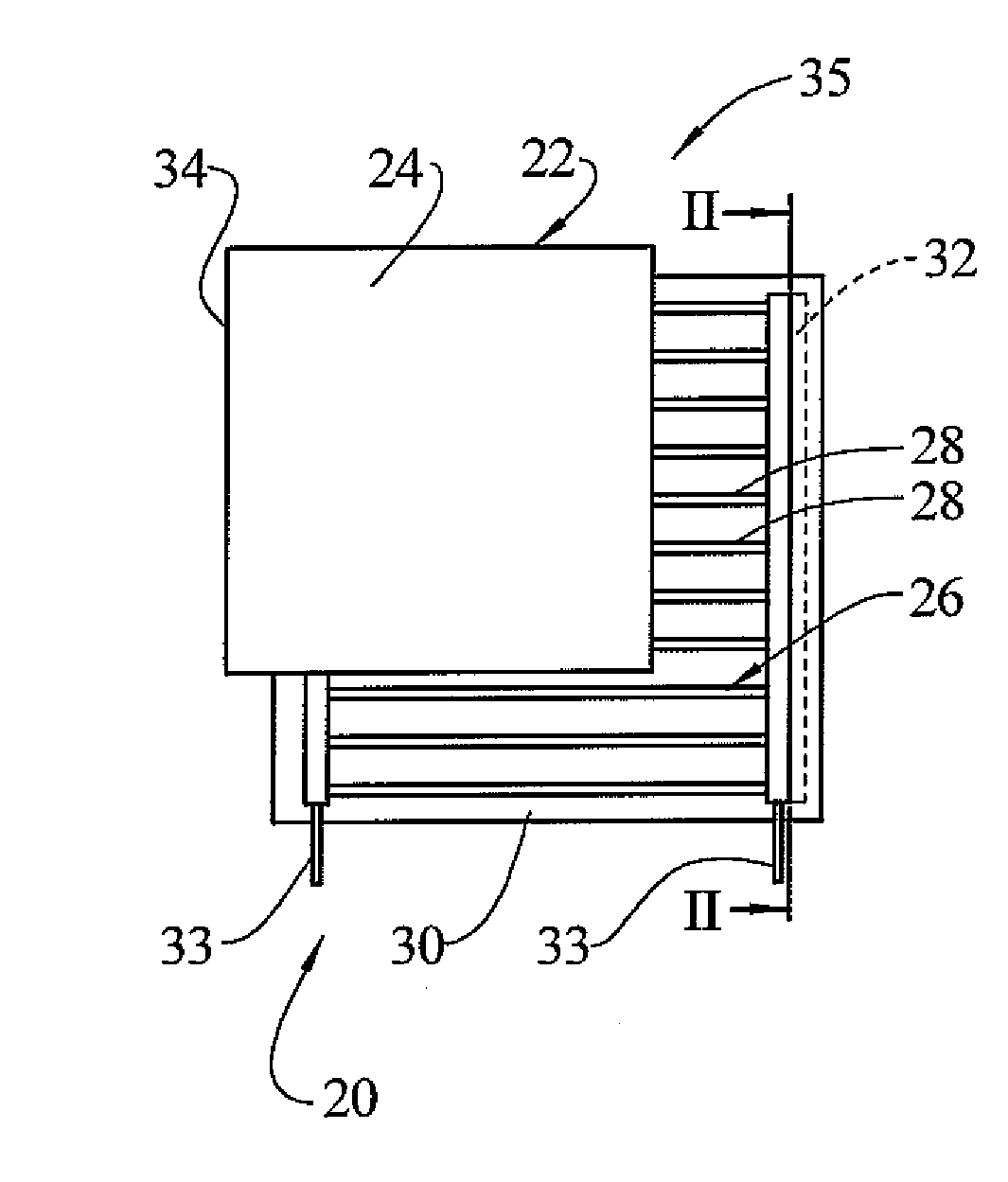
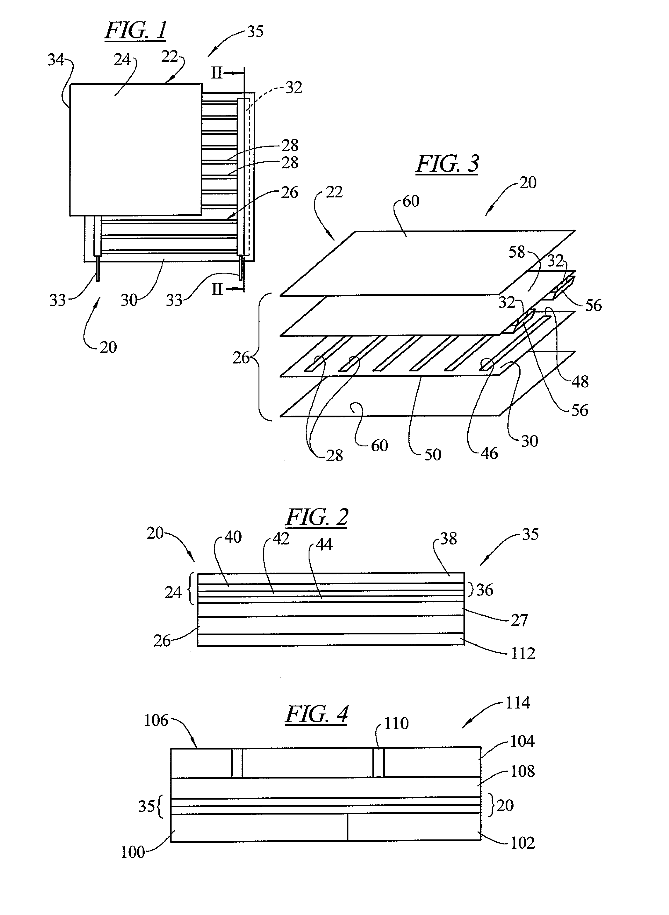
[0041]In an embodiment of the invention, a heating system 20 is provided in the form of a multilayer panel 22. The panel 22 may be thin and flexible with each of the layers not being thicker than 1 to 200 mils. The heating system 20 can be used in a variety of different locations for providing heat to that location. One such location is to use the heating system 20 in a floor. Although the present invention is not limited to such a location, and could also be used in walls, ceilings and other locations, for purposes of providing a description of an embodiment of the invention, it will be described in such a location.

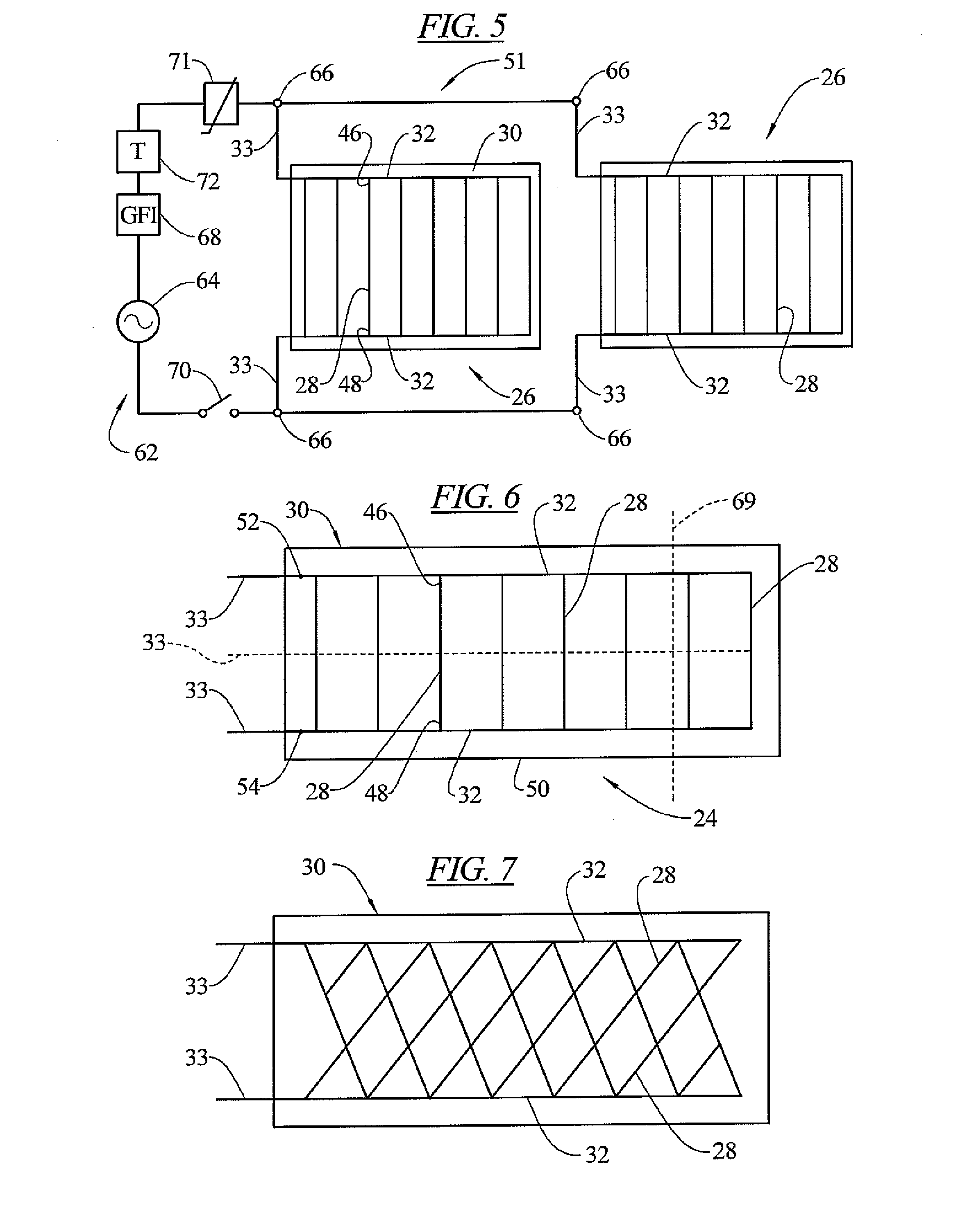
[0042]One of the layers of the panels 22 is a bonding membrane 24 (partially shown in FIG. 1). Another layer is an electrically conductive resistance heater 26. A first adhesive 27 adapted to adhere to both the bonding membrane 24 and the heater 26 may be positioned between the bonding membrane and the heater. In an embodiment, the adhesive 27 could be any adhesive that ...


PUM


Abstract

A heating system which may include a bonding membrane having a water permeable lamina, an electrically conductive ink-based radiant heater, and a first adhesive adapted to adhere to both the conductive ink-based radiant heater and the bonding membrane. The heating system may be incorporated in a floor including a substrate, the heating system and a decorative floor surface. The heating system may also be in the form of a multilayer panel having a bonding membrane, an electrically conductive ink-based heater including a plurality of electrically resistive strips printed on a first polymer sheet connected by electrically conductive buses, and electrical conductors extending from the buses to at least an edge of the panel.

Description

[0001]This application claims priority to provisional applications Ser. No. 61 / 097,323 filed Sep. 16, 2008 and 61 / 176,787 filed May 8, 2009, and incorporated herein by reference in their entireties for all purposes. Patent application entitled “Electrical Heater With A Resistive Neutral Plane” filed simultaneously herewith and including related subject matter is also incorporated herein by reference in its entirety for all purposes.FIELD OF THE INVENTION[0002]This invention relates to heaters that can be installed in buildings such as under conventional decorative flooring. Further, this invention relates to a floor heating system that can be used in wet environments, such as kitchens and bathrooms.BACKGROUND OF THE INVENTION[0003]The use of heating elements in flooring provides a combination of beauty and comfort. Heated floors in cool areas of a building can provide supplemental heat to the space that is evenly distributed. In homes, warmed floors in a bathroom are kind to an occu...

Claims


Application Information

Patent Timeline
Patent Type & Authority Applications(United States)
IPC IPC(8): H05B3/06
CPCH05B3/34H05B2203/003H05B2203/005H05B2203/007H05B2203/026H05B2203/01H05B2203/011H05B2203/013H05B2203/009H05B3/20H05B3/84
Inventor DUBEY, ASHISHMCDONALD, DAVID B.
Owner UNITED STATES GYPSUM CO
Why Eureka
Try Eureka