Steerable, thin far-field electromagnetic beam

a far-field electromagnetic beam and thin-film technology, applied in the field of steering thin-film penetrating electromagnetic beams, can solve the problems of mismatching the size of the object with the size of the object they are trying to achieve, and applying these wavelengths within the limits of visible light penetration

Inactive Publication Date: 2010-03-18
SEIDMAN ABRAHAM N
View PDF17 Cites 11 Cited by
  • Summary
  • Abstract
  • Description
  • Claims
  • Application Information

AI Technical Summary

Benefits of technology

[0050]In the steerable “beam former” an additional magnetic field is applied to the elements of the beam former (in a “two-dimensional” photonic crystal formed from rods, the magnetic field is applied by sourcing a controlled current through a conduit spirally encircling a portion of a “control rod”, which may be ferromagnetic where the magnetic field can be controlled in frequency, amplitude and phase, rod by rod, or collectively for all of the control rods, which may form a subset of all of the rods of the “two-dimensional” photonic crystal. The non-control rods of the two-dimensional photonic crystal may also be non-ferromagnetic metal rods or dielectric non-metal rods. The active beam-former may also use “meta-materials” for that part of the beam former that is not made up of the ferromagnetic control rods.

Problems solved by technology

The difficulty with applying these wavelengths is that they only detect the presence of microstructure (e.g., cancer cells from a biopsy or, anthrax spores on the surface of a letter or package), within the limits of the penetrability of visible light, e.g. on or near surface locations.
One difficulty, however, with longer wavelengths is the mismatch with the size of the objects they are trying to detect.
First attempts to initiate confined beams ran up against energy conservation.
While a patient may have additional magnetic resonance scanning done during the surgery, the results are not simultaneous with the surgery and often may be difficult to perform during a hiatus in the brain surgery.

Method used


Image

  • Steerable, thin far-field electromagnetic beam
  • Steerable, thin far-field electromagnetic beam
  • Steerable, thin far-field electromagnetic beam

Examples


Embodiment Construction

[0057]The following description is of the best mode presently contemplated for carrying out the invention. This description is not to be taken in a limiting sense, but is merely made for the purpose of describing the general principles of the invention. The scope of the invention should be determined with reference to the claims.

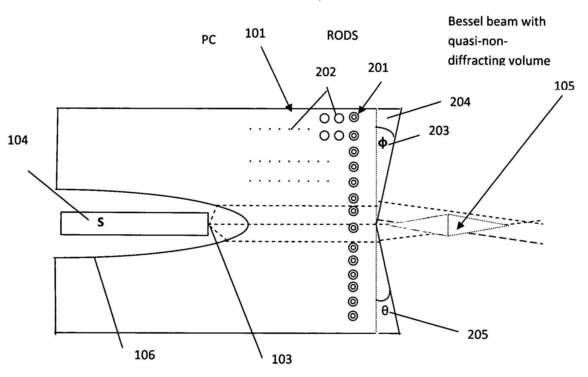
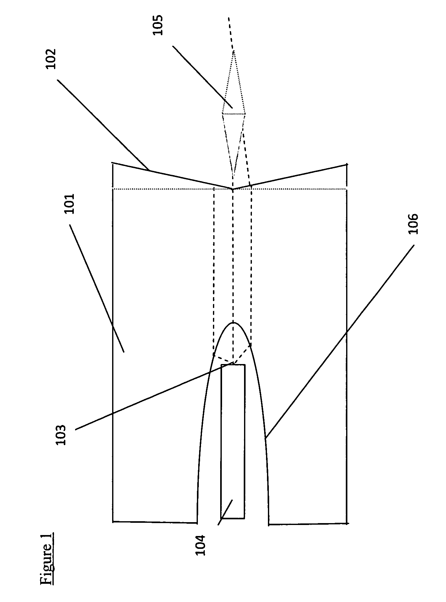
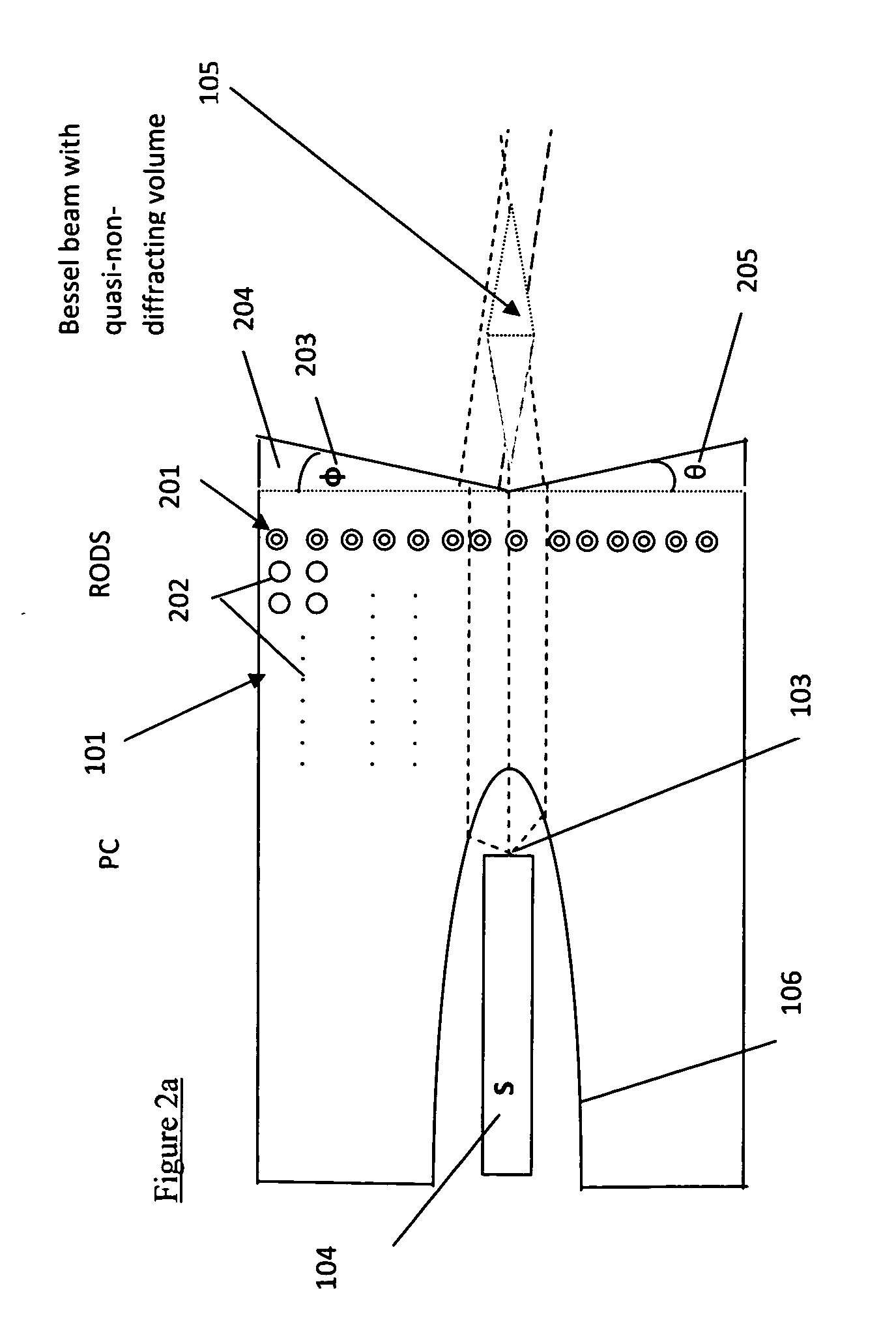
[0058]A system such as FIG. 1 includes a quasi-line source 104, an initial beam shaper 101 with a negative index of refraction arranged with an internal parabola 106 to focus (index of refraction being −1) the line at parabola-focus parallel line into a beam in, for example, a Bloch mode “photonic crystal” (PC) composed of parallel metal wires / rods which has end “rods” of ferromagnetic material, such as soft iron cylinders (RODS), 201 (FIG. 2a) which enable the ends of the PC to initiate a “Bessel-beam” with a very long volume of “quasi-non-diffraction.”

[0059]As shown in FIG. 1, the beam is sourced at a horizontal aperture (descending into the paper, in a tw...


PUM

PropertyMeasurementUnit
diametersaaaaaaaaaa
diameteraaaaaaaaaa
refractive indexaaaaaaaaaa

Abstract

A method and apparatus for forming and controlling a microwave Bessel beam which may be utilized for examining microstructure including very early stage tumors.

Description

[0001]The Applicant claims the benefit of the provisional patent number 60 / ______ filed on Sep. 17, 2007.FIELD OF THE INVENTION[0002]This invention relates to steerable thin penetrating electromagnetic beams utilizing photonic crystals or meta-materials.[0003]This invention relates to detection and identification of microstructures by penetrating electromagnetic radiation of a relatively long wavelength.BACKGROUND[0004]References made throughout this specification are grouped together below. Reference is cited by author [Number], e.g. Aruga [1]:[0005]1. Aruga, T., 1997, “Generation of long-range nondiffracting narrow light beams,” Appl. Opt., Vol. 36, 3762-3768 (1997).[0006]2. Aruga, T., S. W. Li, 1999, “Super high resolution for long-range imaging,” Appl. Opt. Vol. 38, 2795-2799.[0007]3. Aydin, K., I. Bulu, E. Ozbay, 2005, “Focusing of electromagnetic waves by a lefthanded metamaterial flat lens,” 31 Oct. 2005 / Vol. 13, No. 22 / OPTICS EXPRESS 8753[0008]4. Belov, P. A., M. G. Silveiri...

Claims


Application Information

Patent Timeline
Patent Type & Authority Applications(United States)
IPC IPC(8): G02F1/295
CPCA61B18/1815A61B2018/2085G02F2203/24G02F2202/30G02F2202/32A61N5/045H01Q15/0086A61B2018/20351A61B2018/2035
Inventor SEIDMAN, ABRAHAM N.
Owner SEIDMAN ABRAHAM N
Why Eureka
Try Eureka