
Passive optical network system and fault determination method

a passive optical network and fault determination technology, applied in fault recovery arrangements, transmission monitoring, multiplex communication, etc., can solve problems such as communication errors, continuous light emission, and management difficulties, so as to reduce the effect of communication wither other onus, reduce system operation costs, and reduce maintenance time of maintenance engineers

Inactive Publication Date: 2010-03-18
HITACHI LTD
View PDF20 Cites 35 Cited by
  • Summary
  • Abstract
  • Description
  • Claims
  • Application Information

AI Technical Summary

Benefits of technology

[0019]When a fault occurs in an ONU, the PON system and the operation method of the present invention determine the ONU and disconnect it from the PON system operation to minimize the effect on the communication wither other ONUs. In addition, the PON system and the operation method of the present invention reduce the maintenance time of a maintenance engineer in charge of maintaining the PON system, resulting in a reduction in the system operation cost and an increase in the maintenance efficiency.
[0020]When a continuous light is intentionally input to the PON system by a third party with an intention to disrupt the service, the PON system and the operation method of the present invention allow the user to determine the ONU and the light input position quickly and easily and disconnect that part from the OLT, thus increasing the security and reliability of the system operation.

Problems solved by technology

One of the cases where the management becomes difficult as described above is a case where a communication error occurs.
Failure to control an ONU in which an error has occurred sometimes results in a situation in which the ONU continuously emits light and, in the worst case, interferes the communication between other ONUs and the OLT.
At this time, because all ONUs use the common wavelength for the uplink signal, the currently available OLT in a station cannot determine which ONU is emitting light.
However, the procedure for visiting the sites for diagnosing all ONUs and branch optical fibers is time consuming and expensive.

Method used


Image

  • Passive optical network system and fault determination method
  • Passive optical network system and fault determination method
  • Passive optical network system and fault determination method

Examples


Embodiment Construction

[0039]The configuration and the operation of a PON system according to the present invention will be described in detail with reference to the drawings, using an example of the configuration and the operation of GPON defined by ITU-T Recommendation G984.

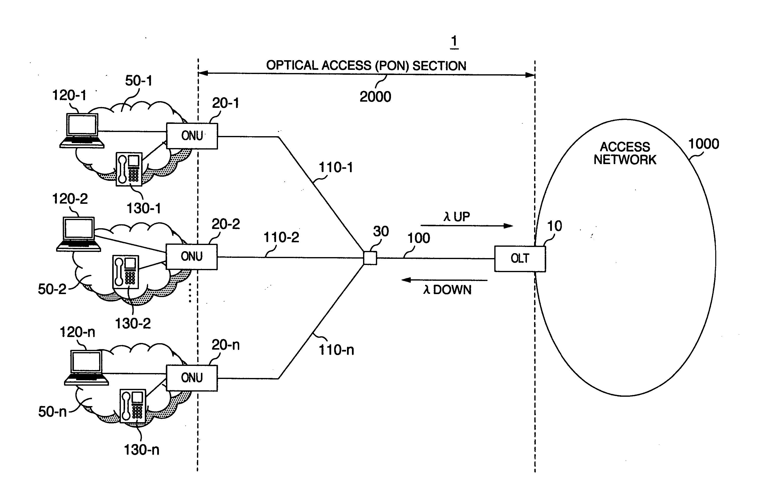
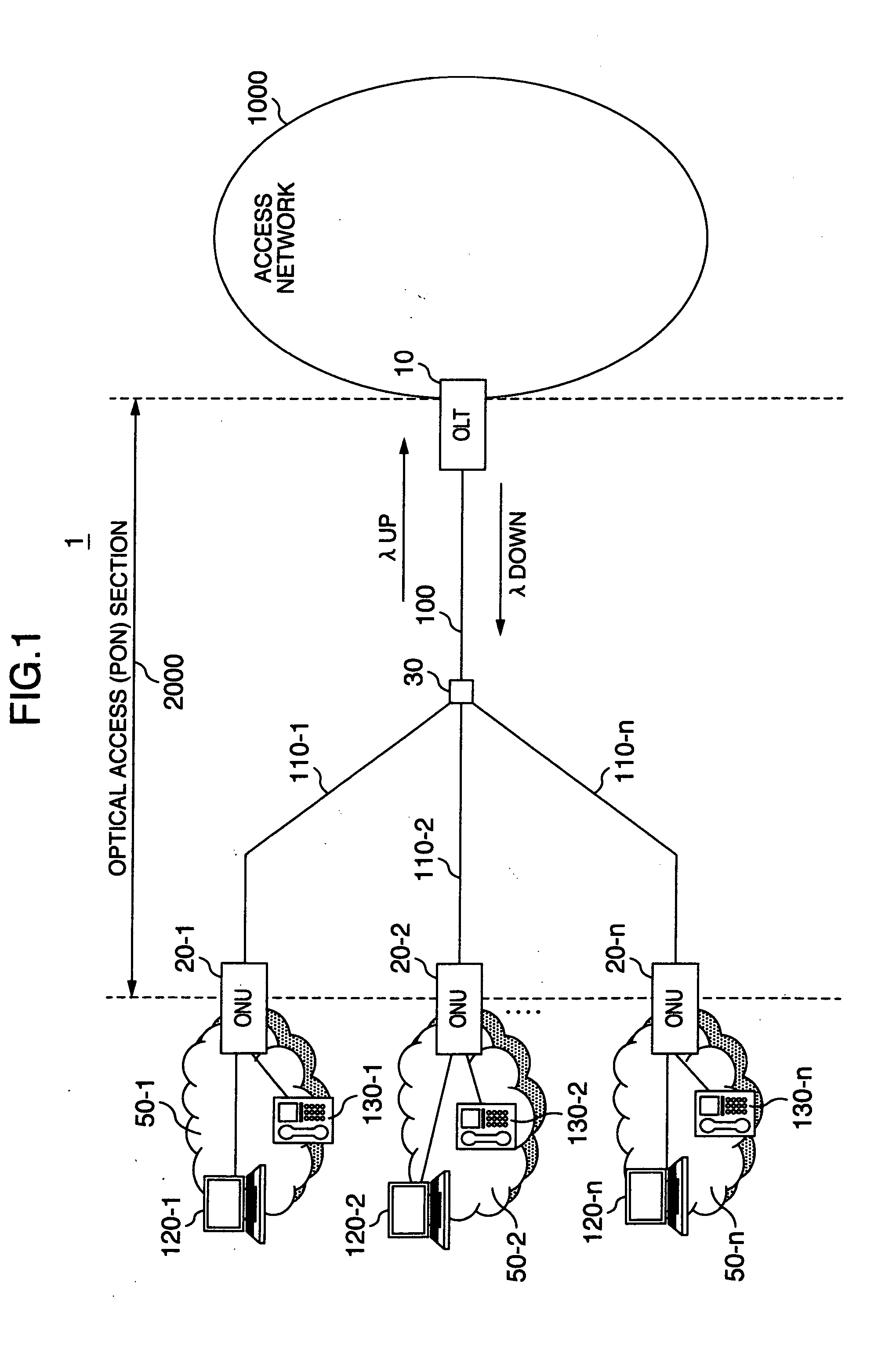
[0040]FIG. 1 is a network configuration diagram showing an example of the configuration of an optical access network using a PON system according to the present invention.

[0041]An optical access network 1 comprises a PON section 2000, which comprises an OLT 10, multiple ONUs 20-1-20-n, an optical splitter 30, a trunk optical fiber 100, and multiple branch optical fibers 110-1-110-n, subscriber networks 50 (or terminals such as a PC 120 and a telephone 130) connected to the ONUs 20, and an access network 1000 that is a higher level communication network.

[0042]The OLT 10 is a communication device, which has an interface to both the PON section 2000 and the access network 1000, sends and receives information to and from the higher-level...


PUM


Abstract

In a passive optical network system, a parent station includes a reception circuit that receives an optical signal from each of child stations using a threshold used to identify if the optical signal is 0 or 1; a bandwidth setting unit that determines a time at which each child station sends an optical signal; a storage unit that stores thresholds and intensities of optical signals received from the child stations; and a control unit that sets a threshold, stored corresponding to a sending time, in,the reception circuit to control a reception of an optical signal. The control unit has a function that compares an intensity of a signal received from each child station at an optical signal reception time with information stored in the storage unit to detect and determine a fault in the child station or in the optical fiber connected to the child station.

Description

INCORPORATION BY REFERENCE[0001]The present application claims priority from Japanese application JP2008-234188 filed on Sep. 12, 2008, the content of which is hereby incorporated by reference into this application.BACKGROUND OF THE INVENTION[0002]The present invention relates to the configuration of a passive optical network system in which multiple optical network units share an optical transmission line and a method for determining a fault occurred in the system.[0003]Recently, FTTH(Fiber To The Home), which is an optical fiber service on access lines that serve subscribers, is introduced, and the communication services provided via this optical access network become more and more diversified as the transmission capacity grows.[0004]An optical communication network called a Passive Optical Network (hereinafter referred to as a PON) has been widely used as an optical access network. This is because the PON system allows multiple users to share an optical fiber, the optical line te...

Claims


Application Information

Patent Timeline
IPC IPC(8): H04B10/08H04J14/02H04B10/075H04B10/07H04B10/079H04B10/27H04B10/272
CPCH04B10/03H04B10/07955H04B10/272H04Q2011/0083H04Q11/0067H04Q2011/0081H04L25/0298
Inventor MIZUTANI, MASAHIKOYAJIMA, YUSUKEASHI, YOSHIHIRO
Owner HITACHI LTD
Learn More