
Photoelectric composite wiring component and electronic apparatus employing it

Active Publication Date: 2010-03-18
HITACHI METALS LTD
View PDF4 Cites 16 Cited by
  • Summary
  • Abstract
  • Description
  • Claims
  • Application Information

AI Technical Summary

Benefits of technology

[0031]According to the present invention, it is possible to compatibly provide both characteristics of the lower power consumption property of the transmission over the electrical wiring and the large transmission capacity of the optical transmission over the optical wiring, by automatically selecting and switching the transmission path to the transmission path to the electrical wiring system or the optical transmission path in accordance with the modulation rate or the transmission rate of the transmission signal. As an example, in a 1.8V power supply operation system, since a power consumption for the optical transmission is assumed to be around 20 mW and the power consumption for the electrical transmission is assumed to be around 5 mW, an effect of reducing the electric power by around 15 mW can be expected, by switching from the optical transmission to the electrical transmission at the time of the low-rate transmission.

Problems solved by technology

In addition, in accordance with downsizing of the electronic apparatus, reduction in width of an electrical wiring component becomes a technical problem.
However, since there is a limit for enhancement of the transmission rate in the electrical wiring, a photoelectric composite wiring component using an optical communication technique is researched as a technique for realizing a large capacity and high speed transmission.
If the optical transmission is used even in the stand-by mode for which the use of a low modulation rate or a low transmission rate is enough, a power consumption of an optical transmitting / receiving section comprising a light emitting element, a light receiving element, and electronic devices for driving the light emitting element and the light receiving element and the like will be large, so that there is a problem in that an operating time, particularly, of a mobile device with a limited power supply capacity is shortened.
Further, when two-way communication is carried out by the optical transmission, it is necessary to prepare electrical wirings and optical wirings in the number required for two-way communication, so that there is a problem in that the number of the electrical wirings is increased.

Method used


Image

  • Photoelectric composite wiring component and electronic apparatus employing it
  • Photoelectric composite wiring component and electronic apparatus employing it
  • Photoelectric composite wiring component and electronic apparatus employing it

Examples


Embodiment Construction

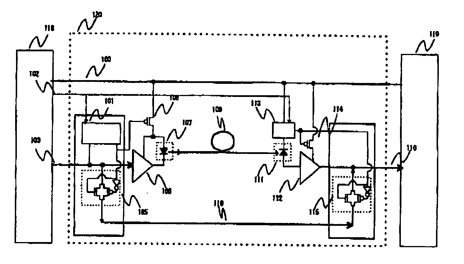
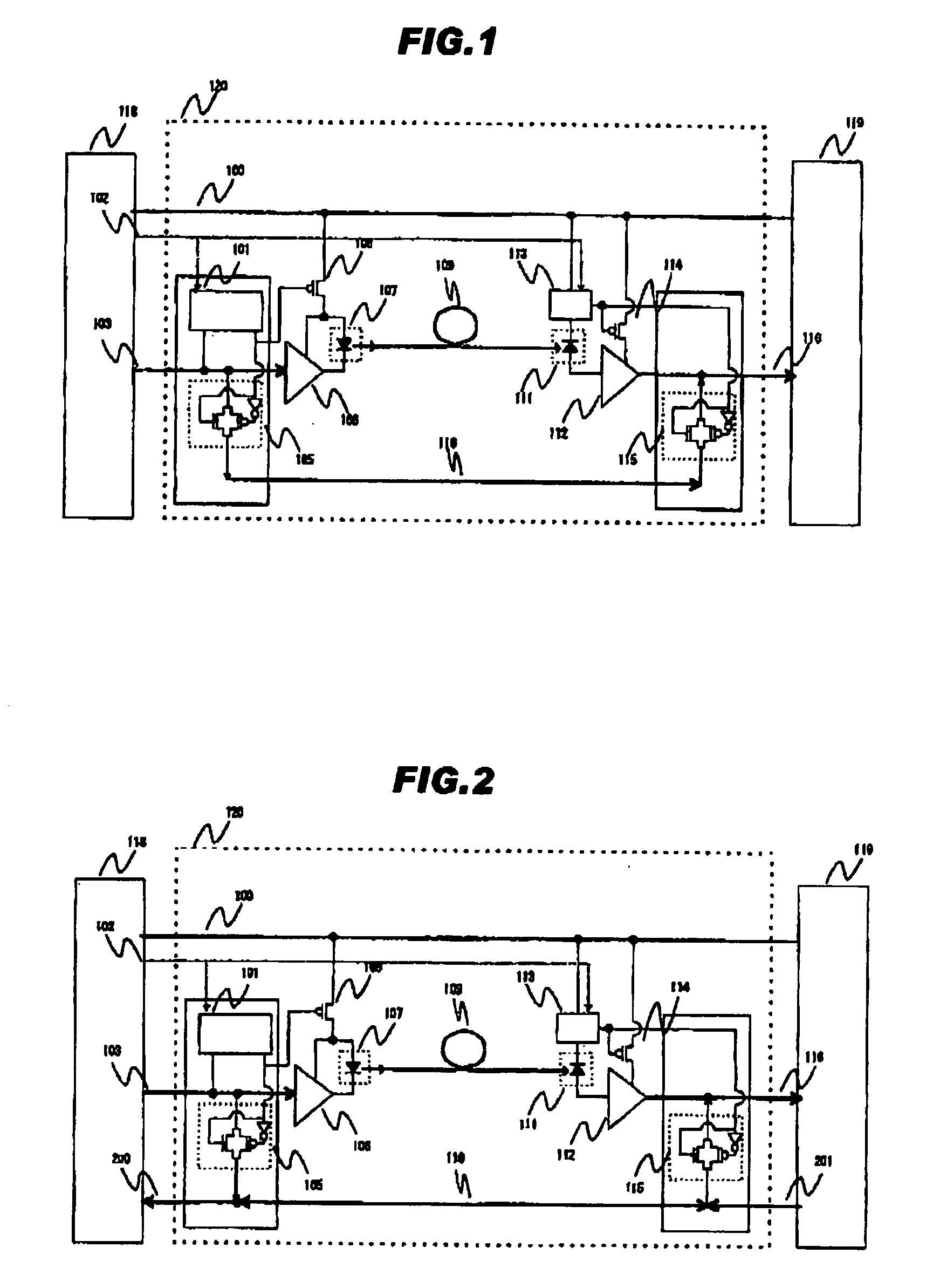
[0101]The first embodiment according to the present invention is explained below with referring to FIGS. 1, and 3 to 7. FIG. 1 is a block diagram of a photoelectric composite wiring component of the present invention. A one-way data transmission structure is configured in which a transmission direction of signals is from a master side 118 (a main body side (a keyboard side) when using a flip type portable telephone as an example) to a slave side 119 (a display side when using the flip type portable telephone as the example).

[0102]At first, a transmission path will be explained.

[0103]A light emitting element drive circuit 106 is a drive circuit which controls a light emission from a light emitting element 107 in accordance with a signal level of a transmission signal line 103, thereby converting an electrical signal to an optical signal. Further, a light receiving element 111 is optically coupled to another end of an optical transmission path 109, and converts the optical signal tran...


PUM


Abstract

To provide a photoelectric composite wiring component combining both characteristics of low power consumption of transmission over electrical wiring and large transmission capacity of optical transmission over optical wiring, and exhibiting a high power efficiency for the transmission capacity. A mechanism for switching between transmission of a transmission signal over an electrical transmission path and that over an optical transmission path depending on the modulation rate or the transmission rate of the transmission signal is provided. When the modulation rate or the transmission rate of the transmission signal is low, power supply to an optical transmitting / receiving section is stopped and the signal is transmitted over the electrical transmission path, thus achieving low power consumption. When the modulation rate or the transmission rate of the transmission signal is high, the signal is transmitted over the optical transmission path, thus achieving a large transmission capacity.

Description

FIELD OF THE INVENTION[0001]The present invention relates to a photoelectric composite wiring component, and more particularly, to a photoelectric composite wiring component having a transmission path switching mechanism for switching a transmission path for a transmission signal to an electrical transmission system or an optical transmission system in accordance with a transmission rate of the transmission signal. Further, the present invention relates to an electronic apparatus using the photoelectric composite wiring component.[0002]This application is based on Japanese Patent Application No. 2006-295701 and entire contents of which is incorporated herein by reference.RELATED ART[0003]Development of the electronic apparatus for conducting a high-resolution moving image transmission is rapidly progressed, so that it is strongly demanded to increase a transmission capacity in appliance wiring. In addition, in accordance with downsizing of the electronic apparatus, reduction in widt...

Claims


Application Information

Patent Timeline
IPC IPC(8): H04B10/00G02B6/122H04B10/25H04B10/80
CPCG02B6/4214H04B10/152H04B10/12G02B6/43H04B10/25891
Inventor FUKASAKU, IZUMIHIRANO, KOKIKOBAYASHI, MASAHIROHIRUTA, AKIHIRO
Owner HITACHI METALS LTD
Learn More