Turbine Blade

a turbine blade and blade technology, applied in the field of turbine blades, can solve the problems of reducing the protection of the blade base body, reducing the service life of the blade, and endangering the operation safety, so as to reduce the downtime of the gas turbine, reduce the effect of impingement cooling, and increase the service li

Inactive Publication Date: 2010-03-18
SIEMENS AG
View PDF5 Cites 22 Cited by
  • Summary
  • Abstract
  • Description
  • Claims
  • Application Information

AI Technical Summary

Benefits of technology

[0024]In a further variant, the heat shield element is connected to the blade basic body in the edge regions of the turbine blade. For foaming the especially effective impingement cooling, the blade basic body, preferably in its leading edge region, is provided with a recess. The advantage of this alternative embodiment lies inter alia in the fact that the original flow-optimized shape of the turbine blade is maintained.
[0025]The described heat shield element can advantageously be used at the places of the turbomachine where component parts and sub-assemblies of the thermal turbomachine are impinged upon with the hot operating medium. However, the use of the heat shield element is especially preferable for the protection of the leading edge region of the turbine blade since the temperature stress of the blade basic body is especially high in this region. Inter alia, the downtimes of the gas turbine are minimized by means of such a heat shield element since the service life is increased because of the heat shield element.
[0026]As a result of the extremely high thermal stress of the heat shield element, cracks can occur in the heat shield element, even when using an especially temperature-resistant material, especially after a specified operating period of the turbine. In this case, for example within the scope of the maintenance operations of the gas turbine, the heat shield elements can be removed in a relatively simple manner and replaced by new ones. Therefore, the affected turbine blades do not have to be completely exchanged as previously in the case of crack development in the leading edge region of the turbine blade.
[0027]The advantages which are achieved with the invention are especially that by means of the heat shield element which is connected upstream to the blade basic body of the turbine blade an efficient protection of the leading edge region of the turbine blade against the high temperatures of the operating medium of the turbines is provided. In particular, such a heat shield system enables the use of impingement cooling, as a result of which the heat shield element can be cooled in an especially effective manner. Furthermore, by means of the heat shield element the possible occurrence of cracks, which extend from the outside surface of the heat shield element and spread into the blade basic body, is prevented. Moreover, the heat shield elements according to the invention can subsequently be attached on the turbine blades in a simple manner and with relatively little cost.

Problems solved by technology

This heat shield, however, has the disadvantage that after a certain time cracks occur in the heat shielding coating.
These cracks reduce the protection of the blade basic body against the hot exhaust gas of the gas turbine so that as a consequence of the increased thermal stress crack development can also occur in the basic body of the turbine blade.
Such cracks in the blade basic body endanger the operational safety and can lead to the breakdown of the gas turbine.

Method used


Image

  • Turbine Blade
  • Turbine Blade
  • Turbine Blade

Examples


Embodiment Construction

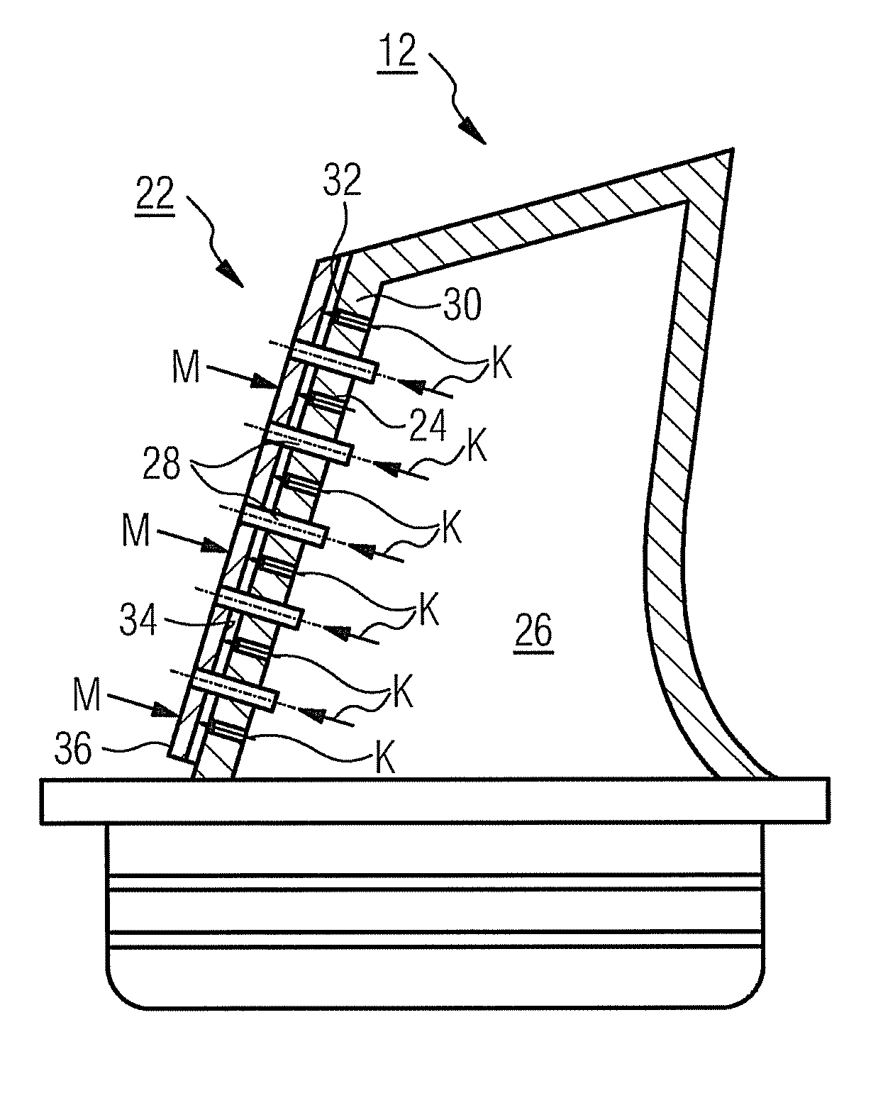
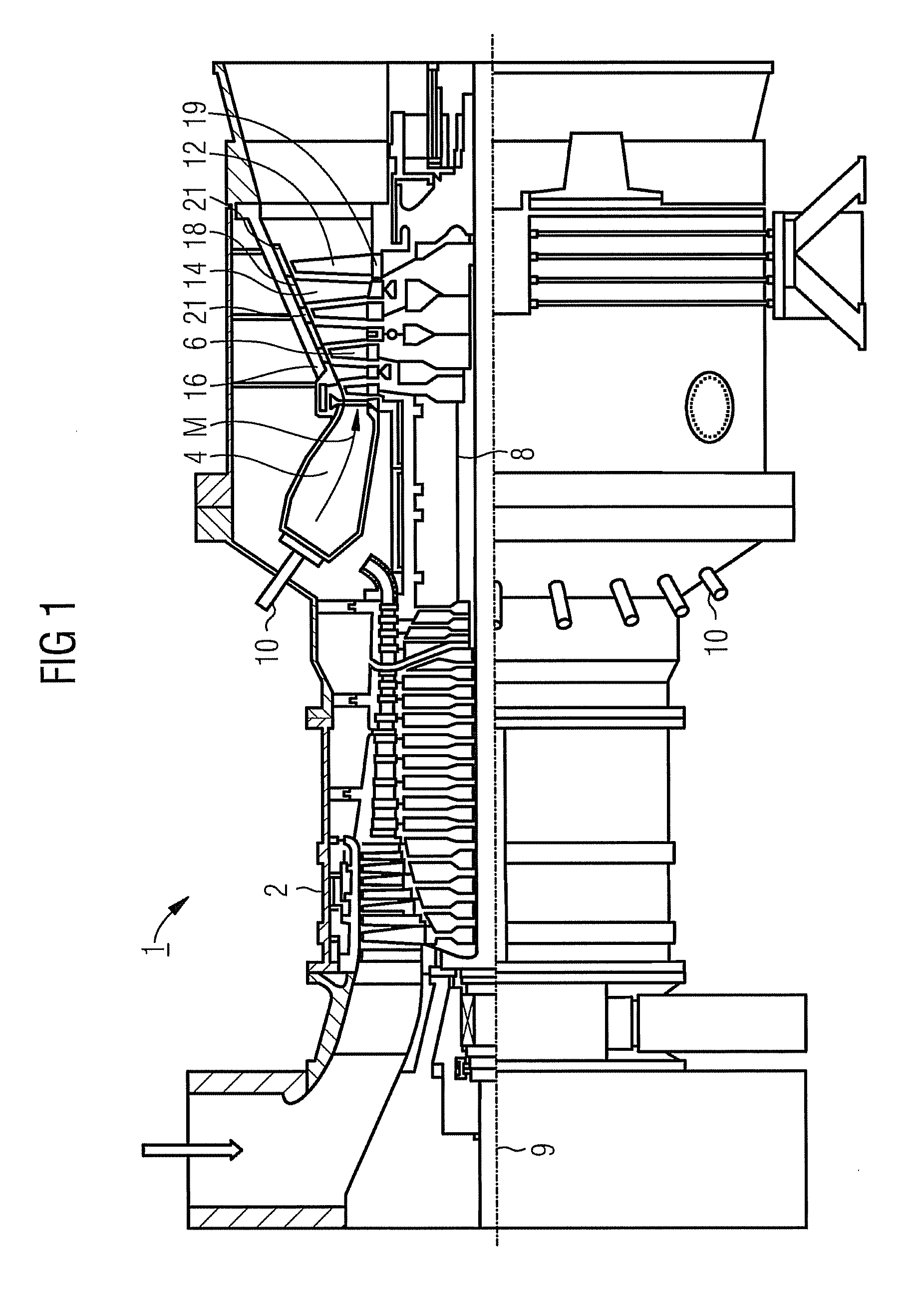
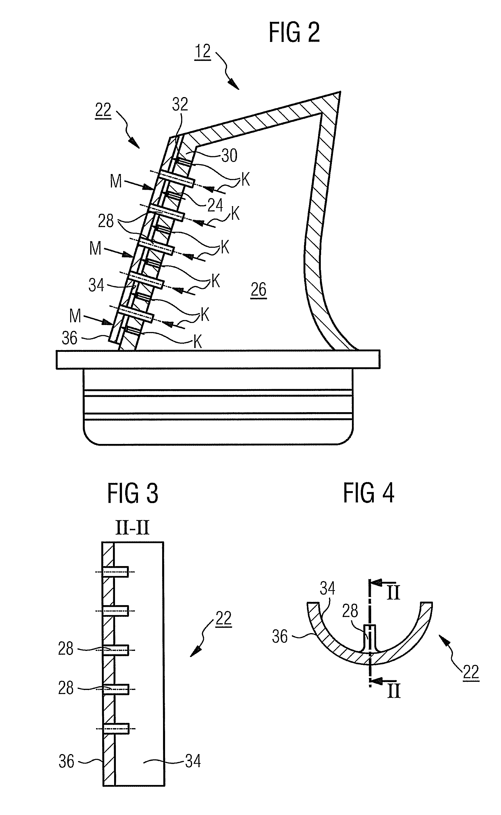
[0036]The gas turbine 1 according to FIG. 1 has a compressor 2 for combustion air, a combustion chamber 4, and also a turbine unit 6 for driving the compressor 2 and for driving a generator, which is not shown, or a driven machine. For this purpose, the turbine unit 6 and the compressor 2 are arranged on a common turbine shaft 8, which is also referred to as a turbine rotor, to which the generator or the driven machine is also connected, and which is rotatably mounted around its center axis 9. The combustion chamber 4, which is designed in the style of an annular combustion chamber, is equipped with a number of burners 10 for combustion of a liquid or gaseous fuel.

[0037]The turbine unit 6 has a number of rotatable rotor blades 12 which are connected to the turbine shaft 8. The rotor blades 12 are arranged on the turbine shaft 8 in the manner of a ring and so form a number of rotor blade rows. Furthermore, the turbine unit 6 comprises a number of fixed stator blades 14 which are fast...


PUM


Abstract

A turbine blade, having a plurality of auxiliary cooling channels which branch off from a main cooling channel, formed within a blade body, is provided. The plurality of auxiliary cooling channels open into outlet openings in the leading edge region of the blade body. A heat shield element is attached to the blade body in the leading edge region at a predefined spacing, wherein the heat shield element has a number of outlet channels which are arranged behind one another in the longitudinal direction and extend from the main cooling channel to the outer wall face of the heat shield element.

Description

CROSS REFERENCE TO RELATED APPLICATIONS[0001]This application is the US National Stage of International Application No. PCT / EP2007 / 059989, filed Sep. 20, 2007 and claims the benefit thereof. The International Application claims the benefits of European Patent Office application No. 06022622.2 EP filed Oct. 30, 2006, both of the applications are incorporated by reference herein in their entirety.FIELD OF INVENTION[0002]The invention refers to a turbine blade according to the claims.BACKGROUND OF INVENTION[0003]Turbomachines, especially gas turbines, are used in many areas for driving generators or driven machines. A gas turbine customarily has a rotatably mounted rotor which is enclosed by a fixed casing. The fixed sub-assemblies of a gas turbine are also collectively referred to as a stator. The energy content of a fuel in this case is used for producing a rotational movement of the rotor components. For this purpose, the fuel is combusted in a combustion chamber, wherein compressed...

Claims


Application Information

Patent Timeline
Patent Type & Authority Applications(United States)
IPC IPC(8): F01D5/18
CPCF01D5/186
Inventor AHMAD, FATHI
Owner SIEMENS AG
Why Eureka
Try Eureka