Composite structure

a composite structure and composite material technology, applied in the field of composite structures, can solve the problem of difficulty in achieving a significant variation in the thickness of the panel between the two stringers

Active Publication Date: 2010-03-18
AIRBUS OPERATIONS LTD
View PDF10 Cites 16 Cited by
  • Summary
  • Abstract
  • Description
  • Claims
  • Application Information

AI Technical Summary

Benefits of technology

[0006]a panel formed from two or more plies of composite material, the panel having a surface formed with a step where the thickness of the panel changes; and
[0007]two or more stiffeners attached to the surface of the panel;

Problems solved by technology

A problem with the structure shown in FIG. 1 is that the ramp 2 must be relatively shallow (typically with a gradient no greater than 1:20 relative to the OML) to avoid load eccentricities.
Consequently it is difficult to achieve a significant variation in panel thickness between the two stringers.

Method used


Image

  • Composite structure
  • Composite structure
  • Composite structure

Examples


Embodiment Construction

)

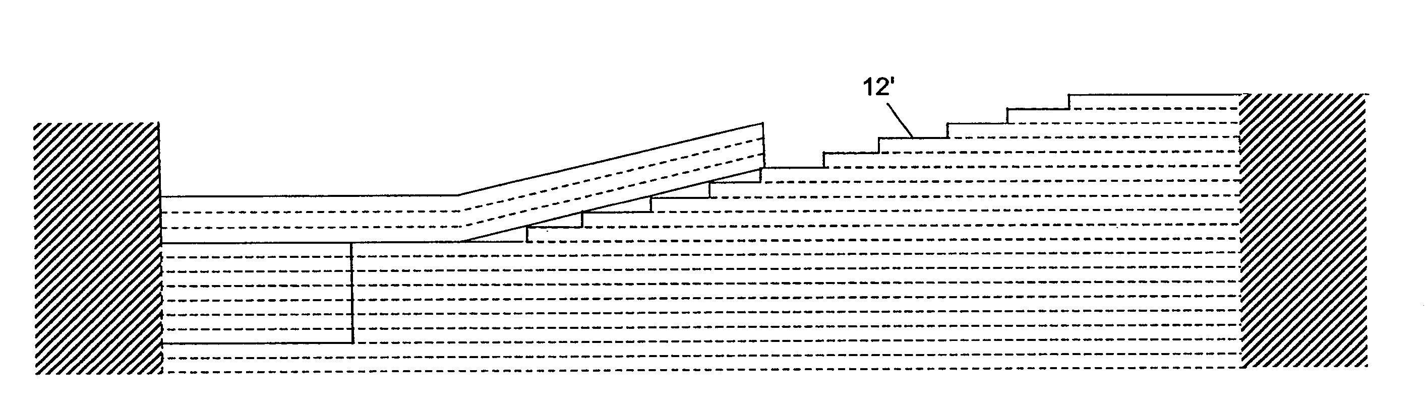
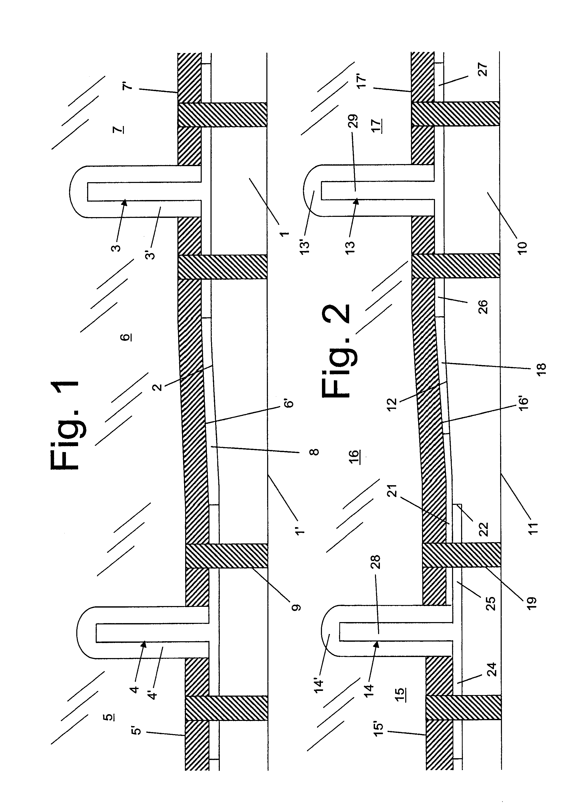
[0027]The composite aircraft skin structure shown in FIG. 2 comprises a panel 10 formed from a stack of plies of composite material. The panel 10 has an inner mould line surface (IML) formed with a step 22 and a ramp 12, and an outer mould line surface (OML) 11 which forms an outer aerodynamic surface of an aircraft. The OML 11 is shown with a flat cross-section in the chordwise direction, although it will be formed with a slight curve in both the spanwise and chordwise directions as required to give the desired aerodynamic characteristics. Since there is no step in the OML 11, the thickness of the panel 10 changes abruptly at the step 22 in the IML.

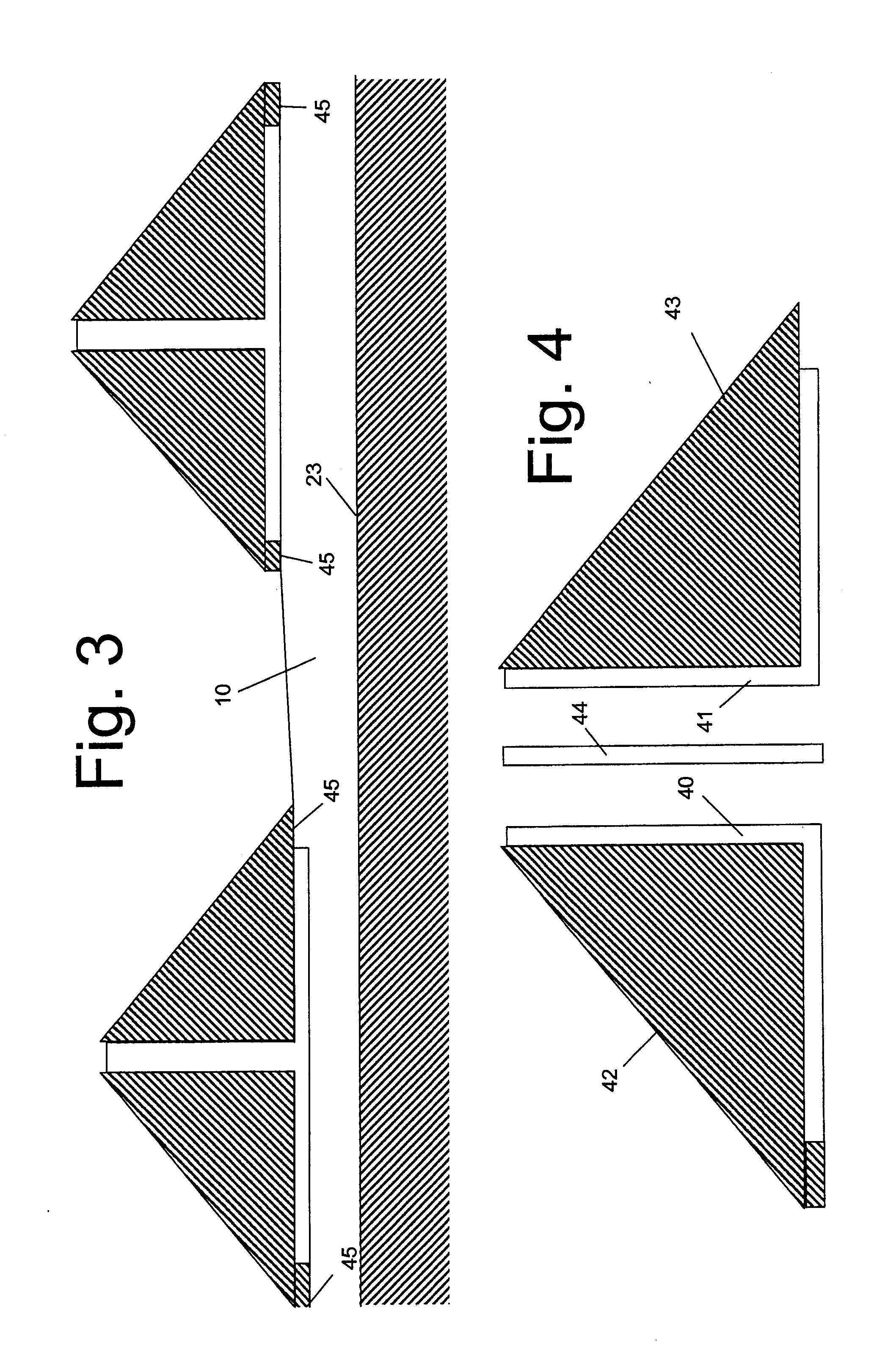
[0028]The panel 10 is formed by laying a stack of plies of “prepreg” (undirectional layers of carbon fibres, pre-impregnated with uncured epoxy resin) on an OML tool 23 shown in FIG. 3. The OML tool 23 is shaped to give the desired profile to the OML. The panel is then “bagged” by placing bagging layers on the panel (namely a peel ply, ...


PUM

PropertyMeasurementUnit
angleaaaaaaaaaa
thicknessaaaaaaaaaa
structureaaaaaaaaaa

Abstract

A composite structure comprising: a panel formed from two or more plies of composite material, the panel having a surface formed with a step where the thickness of the panel changes. Two or more stiffeners are attached to the surface of the panel. One of the stiffeners engages at least part of the step so as to transmit load forces in the panel.

Description

FIELD OF THE INVENTION[0001]The present invention relates to a composite structure, a method of manufacturing a composite structure, and a method of transmitting load in a composite structure. The structure may be, for example, an aircraft skin, but is not limited to such an application.BACKGROUND OF THE INVENTION[0002]The composite aircraft skin structure shown in FIG. 1 comprises a panel 1 with an inner mould line surface (IML) formed with a ramp 2, and an outer mould line surface (OML) 1′ which forms an outer aerodynamic surface of an aircraft. A pair of stringers 3, 4 are attached to the IML, and run spanwise along the length of the panel, stiffening the panel against bending in the spanwise direction.[0003]The skin is joined to a rib via three rib feet 5-7, separated by a pair of “mouse hole” slots 3′,4′ which provide clearance for the stringer blades. Each rib foot 5-7 has a respective flange 5′-7′ extending at right angles to the web of the rib foot. The skin is joined to the...

Claims


Application Information

Patent Timeline
Patent Type & Authority Applications(United States)
IPC IPC(8): B32B3/06B32B3/00B32B37/00
CPCB32B3/02B64C1/12B64C3/24Y10T156/10Y10T428/24479Y10T428/24008Y10T428/24612B64C3/26
Inventor LLOYD, JAMES
Owner AIRBUS OPERATIONS LTD
Why Eureka
Try Eureka